未分类 - Lixin Valve Group Co., Ltd

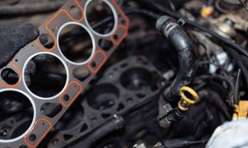
Can A Bad Valve Cover Gasket Cause Check Engine Light?

Have you ever wondered if a bad valve cover gasket can cause the Check Engine Light? This article dives into the importance of the valve cover gasket in preventing oil leaks and engine damage. By understanding the symptoms, causes, and diagnosis of a faulty gasket, you can benefit from early detection and prevention of serious engine issues.

Learning about the role of a valve cover gasket and how it functions can help car owners identify potential problems before they escalate. By recognizing the signs of a failing gasket, such as oil leaks, burning smells, and misfires, individuals can take proactive steps to address the issue promptly. With insights into diagnosis methods and repair options, you can save time and money by maintaining their engine’s health and performance.

Key Points

  • Valve cover gasket seals engine components
  • Leaking oil, burning smell, misfires are symptoms
  • Common causes: age, wear, installation errors
  • Excessive vibration and engine overheating can lead to failure
  • Bad gasket can cause check engine light indirectly
  • Visual inspection, oil level check for diagnosis
  • Compression test for thorough evaluation
  • Repair involves removal, cleaning, and reinstallation
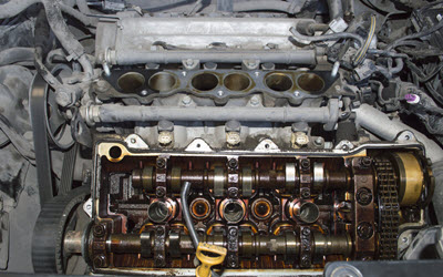
Signs of Valve Cover Gasket Failure
Source: Carotech Automotive

Just How a Valve Cover Gasket Functions

The valve cover gasket is an important component in your automobile’s engine. Situated in between the valve cover and the cyndrical tube head, its key feature is to produce a secure seal. This seal avoids oil from dripping out of the engine and pollutants from entering. The gasket likewise plays a crucial duty in preserving the pressure within the engine, which is needed for optimal efficiency.

The valve cover encloses the top of the engine, covering the valve train, that includes the camshafts, rocker arms, and valves. The gasket not just keeps the oil within the engine however additionally makes sure that the oil is effectively dispersed to the moving parts, reducing friction and wear. This is crucial for the engine’s long life and effectiveness.

Modern valve cover gaskets are commonly made from products like rubber, silicone, or cork, picked for their longevity and ability to withstand heats. Gradually, however, these materials can weaken because of consistent direct exposure to heat, stress, and engine fluids, resulting in gasket failure.

When the valve cover gasket falls short, it can lead to oil leakages, which might not just cause a mess yet likewise lead to substantial engine damage if not addressed promptly. Leaking oil can leak onto the exhaust manifolds, creating smoke and possibly also a fire risk. In addition, not enough oil levels can result in bad lubrication of engine parts, enhancing the danger of severe mechanical problems.

Comprehending exactly how a valve cover gasket functions is vital for diagnosing problems related to it. If you notice signs such as oil leakages, a burning oil scent, or engine misfires, it’s essential to inspect the valve cover gasket as a potential resource of the issue. Addressing gasket problems early can stop more serious and expensive engine damages.

Component Feature
Valve Cover Gasket Develops a seal between the valve cover and cyndrical tube head, protecting against oil leakages and contaminants from entering.
Valve Cover Confines the top of the engine, covering the valve train components.
Materials Usually made from rubber, silicone, or cork for durability and warm resistance.

In summary, the valve cover gasket is a small yet considerable component of the engine’s general capability. Its condition can straight influence the engine’s efficiency and health and wellness, emphasizing the value of routine upkeep and prompt repair work.
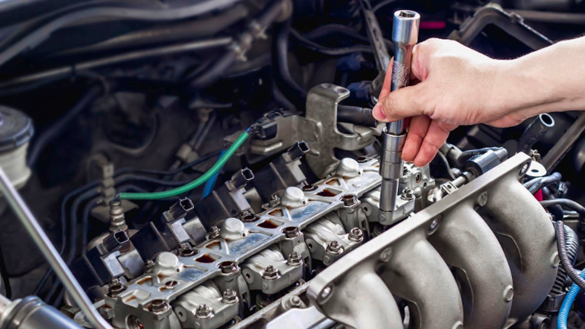
Valve Cover Gasket Replacement Cost
Source: Car Talk

Symptoms of a Poor Valve Cover Gasket

A valve cover gasket is a vital part in your car’s engine, and recognizing the signs of a stopping working gasket can conserve you from much more extreme damage. Among the initial indications is oil leaks. When the gasket wears away, it can no more seal the valve cover properly, leading to oil leaking out. You might see oil spots under your vehicle or oil accumulating around the valve cover.

An additional symptom is the visibility of a burning oil smell. As oil leakages from the defective gasket, it can drip onto warm engine parts, creating a distinctive burning odor. This odor is usually much more visible when the engine is cozy or after driving for a while.

Additionally, a bad valve cover gasket can create the engine to run about or misfire. Oil that leakages from the gasket can pollute the ignition system, bring about inadequate ignition and performance concerns. This contamination can lead to a recognizable reduction in engine efficiency and an increase in gas consumption.

It’s also necessary to check for a check engine light. While a bad valve cover gasket might not straight cause the check engine light, the additional problems it causes, like misfires or oxygen sensor contamination, can. Modern automobiles are geared up with sensing units that discover these troubles, motivating the check engine light to brighten.

Noticeable signs on the engine itself can likewise suggest gasket failing. If you observe oil pooling around the valve cover or sludge accumulation, it’s a clear sign that the gasket is not executing its sealing feature effectively. These visual signs, combined with the other signs and symptoms, can assist in diagnosing a negative valve cover gasket.


Usual Root Causes Of Valve Cover Gasket Failing

A valve cover gasket plays an important duty in sealing the valve cover to the top of the engine cyndrical tube head, preventing oil leakages. However, a number of elements can result in its failing. Understanding these typical reasons can help in identifying and attending to problems quickly.

One of the primary root causes of valve cover gasket failing is age and wear. In time, the gasket product, typically made from rubber or cork, can deteriorate due to constant direct exposure to heats and engine oil. This destruction can cause the gasket to come to be brittle, fracture, or reduce, leading to oil leaks.

One more substantial factor is incorrect setup. If the valve cover gasket is not mounted properly or if the screws are not torqued to the manufacturer’s specs, it can cause an inappropriate seal. This can cause the gasket to fall short prematurely, causing oil leak and prospective engine problems.

Engine overheating is one more typical cause. Excessive warm can cause the gasket material to break down quicker. Overheating can occur as a result of different reasons, such as a malfunctioning air conditioning system, reduced coolant degrees, or a malfunctioning thermostat. When the engine runs hotter than typical, it increases the aging of the gasket.

The visibility of pollutants in the engine oil can additionally add to valve cover gasket failure. Dirt, debris, and sludge can accumulate and create the gasket to wear much faster. Routine oil adjustments and utilizing high-quality oil can assist mitigate this threat.

Furthermore, too much engine vibration can influence the honesty of the valve cover gasket. Resonances from the engine can create the gasket to shift or come to be misaligned, causing leaks. This is typically seen in engines with used or damaged electric motor places or in high-performance cars.

cause Summary
Age and Wear Gasket material wears away gradually because of exposure to warmth and oil
Incorrect Setup Incorrect setup or inappropriate screw torque leads to an incorrect seal
Engine Getting too hot Too much warmth breaks down gasket product faster
Contaminants in Oil Dirt, particles, and sludge cause faster wear of the gasket
Extreme Engine Vibration Vibrations cause the gasket to shift or misalign, resulting in leaks


Can a Poor Valve Cover Gasket cause the Inspect Engine Light?

One common question that develops when dealing with engine issues is whether a negative valve cover gasket can cause the Inspect Engine Light. The valve cover gasket plays an important role in sealing the valve cover to the top of the engine cyndrical tube head. This seal protects against oil from dripping out and contaminating various other engine parts. When the gasket stops working, oil leak is inescapable, which can lead to numerous engine issues.

A falling short valve cover gasket can indeed contribute to the activation of the Examine Engine Light. This generally occurs because the oil leakage causeed by the poor gasket can lead to secondary problems that the lorry’s onboard diagnostics system finds. For instance, oil leaking onto the engine’s ignition system or ignition coils can cause misfires. Engine misfires are an usual reason for the Check Engine Light to light up, as they influence the engine’s efficiency and exhausts.

Additionally, if the leaking oil makes its means to the oxygen sensing units or the catalytic converter, it can cause sensor malfunctions or damages to these essential components. Oxygen sensors are important for keeping track of the engine’s air-fuel mix, and any type of disturbance in their feature can prompt the Check Engine Light to come on. Similarly, oil contamination in the catalytic converter can bring about lowered efficiency or failure, which the vehicle’s diagnostics system will certainly flag.

In summary, while a negative valve cover gasket itself does not directly activate the Check Engine Light, the consequences of the oil leak it causes can cause conditions that do. It is important to resolve a defective valve cover gasket quickly to stay clear of more complications that may lead to an extra extreme and pricey repair service.
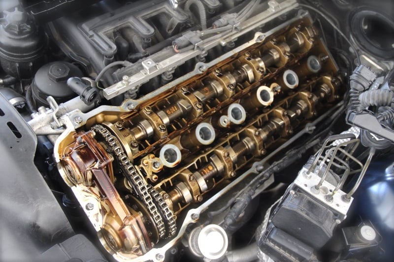
 

Leaking Rocker Cover Gasket - Inspection & Replacement

Detecting a Faulty Valve Cover Gasket

Diagnosing a defective valve cover gasket requires an organized approach to ensure precise recognition and ideal resolution. The primary step in this procedure is to carry out a visual inspection of the valve cover area. Try to find indications of oil leak around the edges of the valve cover gasket. This leakage typically materializes as oil spots or dampness on the engine block and other close-by components.

One more essential analysis action is to inspect the oil degree and condition. A relentless decrease in oil levels without any evident outside leakages could show that the oil is dripping inside as a result of a malfunctioning valve cover gasket. Furthermore, examine the oil for indicators of contamination, such as a milklike look, which suggests that coolant may be blending with the oil as a result of gasket failure.

One of the most telling signs of a negative valve cover gasket is the presence of oil in the spark plug wells. To inspect this, eliminate the stimulate plug cables or ignition coils and check the wells for oil. If oil exists, it is a strong indicator that the gasket has failed, permitting oil to leak into areas where it need to not be.

To even more validate the medical diagnosis, make use of a analysis scan device to examine for problem codes connected to the engine’s performance. While a negative valve cover gasket itself might not straight activate the check engine light, additional concerns caused by the oil leakage, such as misfires or sensing unit breakdowns, can. The check device can assist determine these associated concerns, providing a much more thorough understanding of the trouble.

For a more thorough analysis, think about conducting a compression examination. This examination aids establish the wellness of the engine’s cyndrical tubes and can reveal if the gasket failing has actually led to more considerable inner engine problems. Low compression in several cylinders may indicate that the valve cover gasket failure has actually impacted the cylinder head or valves.

Analysis Action Summary Indicators
Aesthetic Assessment Examine valve cover location for oil leaks Oil spots, dampness on engine block
Oil Degree Check Inspect and keep track of oil levels Persistent decline in oil levels
Ignition System Well Assessment Eliminate ignition system cables and check wells Visibility of oil in cause plug wells
Analysis Check Use check tool to look for difficulty codes Codes associated with misfires or sensor problems
Compression Test Test engine cyndrical tube compression Low compression in cyndrical tubes

By following these diagnostic steps, you can effectively determine a faulty valve cover gasket and understand the degree of the issue. Each action provides essential info that adds to a detailed diagnosis, guaranteeing that the underlying issue is properly attended to.


Fixing and Substitute Options for a Negative Valve Cover Gasket

Addressing a negative valve cover gasket is crucial to keeping your engine’s wellness and stopping additional difficulties. When it comes to fixing or changing a damaged valve cover gasket, there are a number of actions and factors to consider to ensure the process is effective and effective.

Evaluation and Preparation

Prior to beginning any type of repair work or substitute, it is essential to perform a comprehensive assessment. Look for indications of oil leakages around the valve cover area, and examine for any damages to the gasket itself. Gathering the essential tools and components, such as a brand-new gasket, gasket sealer, and ideal wrenches, is important to facilitate a smooth repair process.

Elimination of the Old Gasket

The initial action in the actual repair work is to get rid of the valve cover. This commonly includes loosening the screws that safeguard the cover in location. Meticulously raise the cover off to prevent damaging any type of parts. When the cover is removed, the old gasket can be taken off. Ensure all residues of the old gasket and any type of sealant are completely cleaned up from the valve cover and the engine surface.

Installation of the New Gasket

With the surface areas prepared, you can mount the brand-new gasket. If recommended for your certain car, use a slim layer of gasket sealer to ensure a correct seal. Location the new gasket onto the valve cover, guaranteeing it is correctly lined up. Meticulously position the valve cover back onto the engine, seeing to it the gasket remains in place.

Reassembly and Last Checks

When the new gasket remains in place, reattach the vavle cover by screwing the screws back in. It is essential to tighten the screws in a details sequence, generally beginning from the center and functioning outward, to prevent unequal stress on the gasket. After safeguarding the vavle cover, check for any type of signs of oil leakage around the new gasket. Begin the engine and monitor for any type of unusual audios or leaks.

Action Activity
Examination and Preparation Check for oil leaks and collect required tools and parts.
Removal of the Old Gasket Remove the valve cover and old gasket, clean surface areas.
Installation of the New Gasket Apply gasket sealer if required, put new gasket, placement valve cover.
Reassembly and Last Checks Tighten up screws in turn, check for leaks, begin the engine.

By complying with these steps, you can properly change a negative valve cover gasket and potentially deal with any concerns associated with the check engine light. Normal upkeep and prompt attention to any kind of indicators of gasket failure will assist ensure your engine runs smoothly and efficiently.


Can a Bad Valve Cover Gasket Cause Check Engine Light?

One common question that arises when dealing with engine issues is whether a bad valve cover gasket can cause the Check Engine Light. The valve cover gasket plays a crucial role in sealing the valve cover to the top of the engine cylinder head. This seal prevents oil from leaking out and contaminating other engine components. When the gasket fails, oil leakage is inevitable, which can lead to various engine problems.

A failing valve cover gasket can indeed contribute to the activation of the Check Engine Light. This typically happens because the oil leak caused by the bad gasket can lead to secondary issues that the vehicle’s onboard diagnostics system detects. For instance, oil leaking onto the engine’s spark plugs or ignition coils can cause misfires. Engine misfires are a common reason for the Check Engine Light to illuminate, as they affect the engine’s performance and emissions.

Moreover, if the leaking oil makes its way to the oxygen sensors or the catalytic converter, it can cause sensor malfunctions or damage to these critical components. Oxygen sensors are vital for monitoring the engine’s air-fuel mixture, and any disruption in their function can prompt the Check Engine Light to come on. Similarly, oil contamination in the catalytic converter can lead to reduced efficiency or failure, which the vehicle’s diagnostics system will flag.

In summary, while a bad valve cover gasket itself does not directly cause the Check Engine Light, the consequences of the oil leakage it causes can lead to conditions that do. It is essential to address a faulty valve cover gasket promptly to avoid further complications that might result in a more severe and costly repair.

Key Features and Applications of Big Size Ball Valves

Reading this article on big size ball valves will provide valuable insights into the key features, materials, and applications of these essential components. As an expert in the field, I have highlighted the critical design elements, material options, and performance metrics that are crucial for selecting the right valve for various industries. By understanding these aspects, you can make informed decisions and ensure efficient and reliable operation in their systems.

Furthermore, the article covers installation and maintenance tips, comparison to other valve types, and selection criteria, offering a comprehensive guide for you. Whether you are involved in the oil & gas industry, chemical plants, water treatment facilities, power generation, or marine applications, the information provided will help you choose the most suitable large size ball valve for your specific needs, ensuring optimal performance and longevity in your operations.

Key Points

  • High flow capacity, tight shut-off
  • Materials: stainless steel, carbon steel
  • Design: full port, floating/trunnion ball
  • Actuation options: manual or automated
  • Applications: oil & gas, chemical plants
  • Installation: proper alignment, support
  • Maintenance: regular inspection, lubrication
  • Comparison to other valve types
  • Selection criteria: application, material, size
  • Consult experts for tailored recommendations


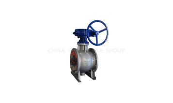
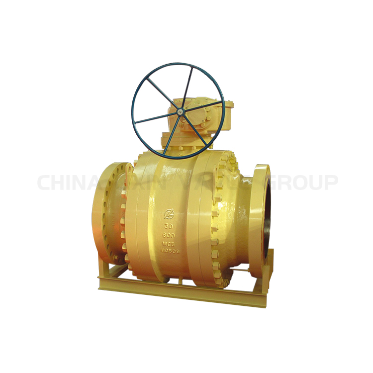
Trunnion Ball Valve Manufacturer, Supplier
Source: Lixin Valve

Secret Features of Big Size Ball Valves

As an expert in the field, I have actually experienced countless large size ball valves throughout my career, and numerous essential features consistently attract attention. These features are critical for ensuring the efficient and reputable operation of these valves in various applications.

Big size ball valves are designed to manage large circulation capabilities and high pressures. The key function that differentiates them from smaller sized valves is their capability to provide a limited shut-off, which is vital for avoiding leakages in essential systems. This is accomplished through using a ball valve with a bore via the facility, which can turn to open up or shut the valve.

Products and Construction

Large size ball valves are created from robust products to withstand rough operating conditions. Typical materials consist of:

Material Quality
Stainless-steel Deterioration resistance, high toughness
Carbon Steel Longevity, cost-effectiveness
Brass Good deterioration resistance, moderate stamina
PVC Lightweight, chemical resistance

Style Functions

A number of layout features are important to the performance of large size ball valves:

  • Complete Port Style:This style makes sure that the valve bore coincides diameter as the pipeline, decreasing stress decrease and permitting maximum circulation.
  • Drifting or Trunnion Mounted Round:Depending on the dimension and stress demands, the valve might be drifting (for reduced to tool stress applications) or trunnion mounted (for high pressure applications).
  • Sealing Devices:High-quality seals, often made from PTFE or other durable products, give tight shut-off and long solution life.
  • Actuation Options:Large size ball valves can be manually run or geared up with actuators (electrical, pneumatically-driven, or hydraulic) for remote control and automation.

Performance Metrics

Performance metrics for big size ball valves typically include:

Metric Normal Array
Dimension Range 2″ to 56″ (or larger)
Pressure Rating 150 psi to 2500 psi
Temperature Range -29 ° C to 200 ° C(depending on materials)
Flow Coefficient (Curriculum Vitae) Differs based on size and design

Comprehending these key functions is necessary for picking the proper large size ball valve for your particular application, making sure both efficiency and integrity in your system’s operation.


Materials Utilized in Manufacturing Big Size ball valves

When it pertains to the production of large size ball valves, the selection of materials is important to make certain resilience, performance, and safety and security. These valves are typically used in high-pressure and high-temperature atmospheres, making product option a basic element of their layout and capability.

One of the most usual products made use of in the construction of big size ball valves is stainless steel. Stainless-steel is preferred for its superb rust resistance, high toughness, and capability to endure extreme temperature levels. It is particularly suitable for applications entailing hostile chemicals or destructive atmospheres, making it a functional option for numerous sectors.

Carbon steel is an additional often utilized material, specifically in situations where cost-effectiveness is a top priority. While it might not supply the exact same level of deterioration resistance as stainless-steel, carbon steel provides substantial stamina and is ideal for a large range of applications, consisting of oil and gas pipelines, water therapy plants, and industrial procedures.

Sometimes, alloy steels are employed to boost specific buildings of the ball valve, such as solidity, tensile toughness, and put on resistance. By integrating elements like chromium, molybdenum, and nickel, alloy steels can offer better efficiency under harsh conditions, including high-pressure and high-temperature applications.

For applications that demand remarkable corrosion resistance, duplex stainless-steels and extremely duplex stainless-steels are typically chosen. These products incorporate the advantages of austenitic and ferritic stainless-steels, supplying remarkable strength and resistance to stress deterioration fracturing, matching, and crevice corrosion.
In addition to steels, non-metallic products such as PTFE (polytetrafluoroethylene) and various other design plastics are utilized for parts like seats and seals within big size ball valves. These materials use reduced friction, high chemical resistance, and the ability to preserve stability over a broad temperature level variety, contributing to the reputable procedure of the valve.

Lastly, for specialized applications, unique alloys such as Hastelloy, Inconel, and Monel might be used. These products are designed to withstand exceptionally aggressive settings, consisting of very acidic or alkaline conditions, and supply unequaled resistance to oxidation and corrosion at elevated temperature levels.

Comprehending the properties and benefits of these materials is essential for picking the proper big size ball valve for particular applications. The right product option boosts the valve’s life-span, performance, and integrity, guaranteeing it fulfills the strenuous needs of commercial processes.


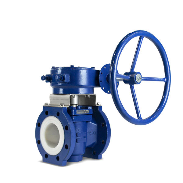
Gear Operated Flanged End Lined Ball Valve at Rs 3500/piece | Ball Valve With Flange

Common Applications of Large Size ball valves

Big size ball valves are essential components in various markets because of their capability to handle large quantities of fluid and their trustworthy securing properties. These valves are commonly utilized in the adhering to applications:

Oil and Gas Industry

In the oil and gas market, large size ball valves are necessary for controlling the flow of petroleum, gas, and fine-tuned items. They are utilized in pipes, processing plants, and storage space facilities where longevity and high circulation capacity are vital.

Chemical and Petrochemical Plants

Chemical and petrochemical plants use large size ball valves to manage the circulation of various chemicals and petrochemical products. These valves are selected for their resistance to harsh substances and their ability to keep a tight seal under high stress and temperature level conditions.

Water Therapy and Distribution

In water treatment plants and distribution systems, large size ball valves play a pivotal duty in regulating the flow of water. They guarantee reliable water monitoring in metropolitan supply systems, wastewater treatment facilities, and watering networks.

Power Generation

Power plants, consisting of thermal, nuclear, and hydroelectric centers, rely upon big size ball valves to manage the flow of heavy steam, water, and other fluids. These valves are crucial for maintaining operational safety and security and efficiency in power generation procedures.

Marine and Offshore Applications

In marine and overseas environments, large size ball valves are made use of in systems for dealing with ballast water, gas, and various other crucial liquids. Their robust building and construction and capability to endure severe conditions make them appropriate for usage on ships, oil well, and other offshore systems.

Sector Application Secret Conveniences
Oil and Gas Pipeline control, handling plants High flow capability, sturdiness
Chemical and Petrochemical Flow monitoring of chemicals Rust resistance, tight seal
Water Therapy Water guideline in treatment plants Efficient water monitoring
Power Generation Vapor and water flow control Functional safety, efficiency
Marine and Offshore Taking care of ballast water, fuel Durable building, withstand rough problems


Installment and Maintenance Tips for Big Size Ball Valves

When setting up large size ball valves, it is crucial to make certain correct placement with the piping system to stay clear of unneeded anxiety on the valve body and pipeline. Appropriate support of the valve and nearby piping is important to keep structural honesty and performance. It is suggested to use training tools to handle these huge and hefty components securely.

Setup Tips

Before installment, evaluate the big size ball valve for any problems or debris that could harm its procedure. Make certain that the valve remains in the totally shut setting to secure the round and seats throughout setup. Use proper gaskets and sealing materials to stop leakages. It is likewise important to comply with the manufacturer’s torque specifications for flange bolts to accomplish a secure and leak-free connection.

Maintenance Tips

Normal upkeep of large size ball valves is important to ensure their long-lasting efficiency and reliability. Periodic examination ought to consist of looking for leaks, verifying the operation of the valve, and evaluating the problem of the seals and seats. Lubing the valve stem and other relocating parts can assist keep smooth operation and avoid wear.

For valves utilized in crucial applications, it is suggested to carry out a precautionary upkeep routine. This might include much more regular assessments and servicing, relying on the operating problems and the maker’s referrals. Replacing worn or broken components without delay can assist avoid more significant issues and expand the valve’s service life.

In recap, the efficient installment and maintenance of big size ball valves include careful handling, normal inspection, and adherence to supplier standards. By adhering to these techniques, you can ensure reliable procedure and long life of these crucial parts in your piping system.


Comparing Large Size ball valves to Other valve Types

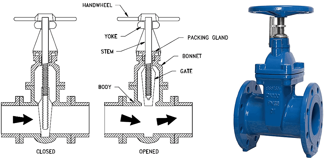
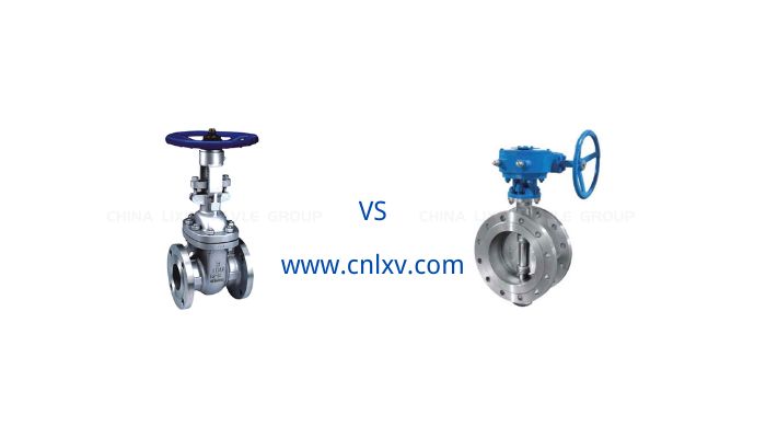
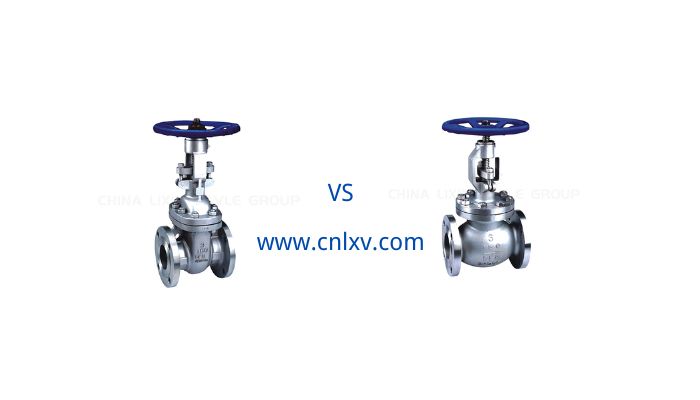
When examining different valve types for industrial applications, it’s critical to recognize exactly how big size ball valves contrast to various other typical valve kinds, such as gate valves, globe valves, and butterfly valves. Each valve type has its unique features, benefits, and limitations, which can substantially impact efficiency, upkeep, and suitability for particular applications.

Circulation Control and Performance

Big size ball valves are extremely reliable in providing tight shut-off and dependable circulation control. The spherical layout permits for quick opening and closing, which reduces pressure decline throughout the valve. In contrast, entrance valves, while additionally supplying excellent shut-off capabilities, tend to have a higher stress decrease as a result of eviction’s activity via the flow course. World valves, developed for accurate flow regulation, naturally have greater stress decreases since of their tortuous flow course. Butterfly valves, with a disc that revolves within the flow, supply a reduced stress decrease comparable to ball valves yet might not give as limited a seal.

Toughness and Upkeep

In regards to longevity, huge size ball valves are understood for their robust layout and marginal maintenance demands. The ball system is less vulnerable to damage contrasted to the gate device in entrance valves, which can struggle with disintegration and deterioration gradually. World valves require even more constant upkeep due to their complex style and the constant friction between the disc and seat. Butterfly valves, while generally long lasting, can experience concerns with the disc seal gradually, specifically in high-pressure applications.

Setup and Room Factors To Consider

When it concerns installment, big size ball valves are relatively simple and call for much less area than gateway valves, which require space for eviction to climb and drop. Globe valves also need more space due to their style and the need for linear stem movement. Butterfly valves are small and require the least amount of area, making them suitable for installations with limited area.

Price and Application Viability

Price is a significant aspect in selecting the ideal valve. Typically, big size ball valves are much more pricey than gate and butterfly valves yet offer premium performance and durability, validating the higher preliminary investment. World valves have a tendency to be expensive because of their complex layout however are vital for applications calling for exact circulation control. The selection of valve must align with the particular needs of the application, considering variables such as running pressure, temperature level, and the nature of the liquid being managed.

Valve Type Circulation Control Efficiency Sturdiness Space Demands Cost Application Suitability
Big Size Ball valve High High Modest High General, High-Performance Applications
Gate valve Moderate Moderate High Reduced to Modest General Shut-off Applications
Globe valve High Moderate High High Specific Circulation Control
Butterfly valve Modest Moderate Reduced Reduced Space-Constrained Installments


 Carbon Steel Globe Valve, Size: 10 Inch at Rs 43000/piece

How to Select the Right Big Size Ball Valve for Your Requirements

Choosing the best big size ball valve for your details needs includes evaluating a number of critical factors to make sure ideal performance and long life. The following standards will certainly assist promote an educated decision-making process.

Understand Your Application Requirements

Most importantly, consider the certain application for which the large size ball valve is meant. This includes recognizing the sort of fluid or gas that will stream through the valve, the operating pressure and temperature conditions, and the called for flow rate. These parameters will considerably influence the selection of materials and layout functions.

Material Selection

The product of the valve body and interior components ought to be suitable with the liquid or gas to avoid rust and ensure resilience. Common materials for big size ball valves include stainless steel, carbon steel, and different alloys. The selection of material affects not only the valve’s durability however additionally its efficiency under particular conditions.

Valve Size and Pressure Score

Make certain the valve size matches the pipe size to maintain optimum circulation features and minimize stress drop. Additionally, the pressure rating of the valve should go beyond the maximum operating stress of the system to guarantee safety and reliability. Refer to the table below for common size and stress ratings:

Valve Dimension (inches) Stress Score (psi)
2 – 4 150 – 300
6 – 12 150 – 600
14 – 24 150 – 900
26 – 48 150 – 1500

Think About the Actuation Technique

The approach of actuating the big size ball valve is another crucial factor to consider. Alternatives consist of guidebook, electrical, pneumatically-driven, and hydraulic actuators. The option depends on the level of automation desired, the readily available power sources, and the certain control needs of the application.

Top Quality and Compliance Specifications

Guarantee that the valve meets pertinent market criteria and certifications, such as API, ANSI, or ISO. Conformity with these requirements assurances that the valve has actually undertaken strenuous screening and follows top quality production practices.

Spending Plan and Overall Cost of Ownership

While in advance cost is an essential aspect, also consider the total price of ownership, which consists of setup, maintenance, and prospective downtime prices. Spending in a higher-quality large size ball valve may cause lower long-lasting costs because of enhanced reliability and minimized maintenance requirements.

Seek advice from Specialists

Ultimately, seek advice from valve makers or industry professionals to get insights and referrals tailored to your certain demands. Their expertise can aid recognize one of the most appropriate large size ball valve and ensure it meets the functional demands of your system.

By meticulously considering these factors, you can select the appropriate big size ball valve that supplies ideal performance, integrity, and cost-efficiency for your application.


FAQs about Big Size Ball Valves

What are the key features of big size ball valves?

Big size ball valves are designed to handle large flow capacities and high pressures, providing a tight shut-off to prevent leaks. They are constructed from materials like stainless steel, carbon steel, brass, and PVC, and feature a full port design, floating or trunnion mounted ball, high-quality sealing mechanisms, and various actuation options.

What materials are used in manufacturing big size ball valves?

Big size ball valves are commonly made from materials like stainless steel, carbon steel, alloy steels, duplex stainless steels, super duplex stainless steels, and non-metallic materials such as PTFE. Exotic alloys like Hastelloy, Inconel, and Monel are also used for specialized applications.

What are the common applications of big size ball valves?

Big size ball valves are used in various industries, including oil and gas, chemical and petrochemical plants, water treatment and distribution, power generation, and marine and offshore applications. They are essential for controlling the flow of fluids in pipelines, processing plants, and other critical systems.

What are some installation and maintenance tips for big size ball valves?

During installation, it’s important to ensure proper alignment, support, and use of appropriate gaskets and sealing materials. Regular maintenance involves inspecting for leaks, verifying operation, lubricating moving parts, and following a preventive maintenance schedule to replace worn or damaged parts promptly.

How do big size ball valves compare to other valve types?

Big size ball valves offer high flow control efficiency, durability, moderate space requirements, and a higher cost compared to gate, globe, and butterfly valves. Each valve type has its unique features and suitability for specific applications based on factors like flow control, durability, space requirements, and cost.

How can I select the right big size ball valve for my needs?

To select the right big size ball valve, consider factors such as application requirements, material selection, valve size and pressure rating, actuation method, quality and compliance standards, budget, and total cost of ownership. Consulting with experts can also provide valuable insights and recommendations tailored to your specific needs.

PSI vs PSIG

What is PSI?

PSI is a widely used unit of pressure measurement in the United States and other countries. It quantifies the force exerted over an area of one square inch. Unlike the Pascal (Pa), the SI unit of pressure that measures force in Newtons per square meter, PSI utilizes pounds-force per square inch. This unit is vital in various scientific, engineering, and industrial contexts where precise pressure measurement is crucial. PSI vs PSIG

The concept of PSI is straightforward: applying one pound of force to a one-square-inch area results in one PSI of pressure. This metric helps quantify the intensity of the applied force over a specified area, making it an invaluable tool for assessing pressure in different systems.

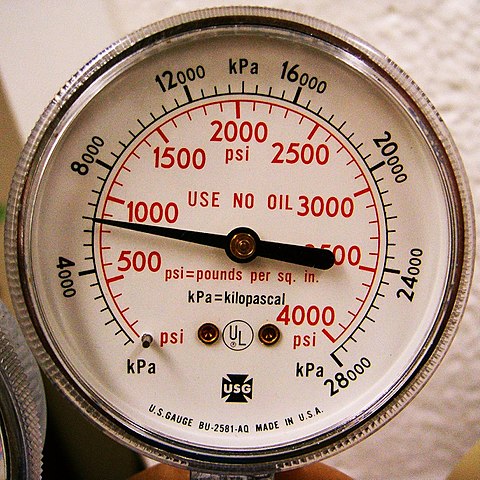
To put PSI in perspective, 1 PSI is equivalent to 0.068046 atmospheres, 0.0689476 bar, and 6894.76 Pascals. These conversions are essential for comparing PSI to other global pressure units. It’s also important to distinguish PSI from PSIG, which measures pressure relative to atmospheric pressure, as opposed to absolute pressure.

PSI is a fundamental unit of pressure measurement, offering a clear and precise method to quantify force over a specific area. Understanding PSI and its equivalents in other pressure units is essential for accurate pressure measurement and effective communication across various fields and applications.


What is PSI
Source: Wikipedia

Where is PSI Used?

PSI is a common unit of measurement for pressure and is used in a wide variety of industries and fields. The use of PSI is especially important in the manufacture of industrial valves. Industrial valves, such as butterfly, ball, and gate valves, are required to operate in different pressure environments. By measuring and specifying the performance of valves at different PSI values, their safety and reliability under various operating conditions can be ensured.

In the oil and gas industry, PSI is used to measure the pressure inside pipelines and storage tanks to ensure the safe operation of equipment and processes in high-pressure environments. Industrial valve manufacturers need to design and test valves to different PSI ratings to meet specific customer needs. For example, valves used in high-pressure natural gas transmission must be able to withstand thousands of PSI.

In the water and wastewater treatment industry, PSI is used to monitor pressure in pumping stations and piping systems. Manufacturers of industrial valves need to ensure that the valves will function properly without leaking or malfunctioning when handling water and wastewater under a variety of pressure conditions. By using PSI values, engineers can optimize system design, improve efficiency and reduce energy consumption.

In the chemical and pharmaceutical industries, PSI is used to measure pressure in reactors, piping and other equipment. Industrial valves in these industries must be able to operate at high temperatures and pressures to ensure safe and efficient chemical reactions. Manufacturers need to ensure the durability and reliability of valves in high PSI environments through rigorous pressure testing.

Moreover, PSI is also widely used in aerospace, automotive manufacturing, and food and beverage processing. In these industries, industrial valves must operate under specific pressure conditions to ensure the safety and stability of the system.PSI, a universal unit of pressure measurement, provides reliable data to support engineering design and equipment manufacturing in a variety of industries. In industrial valve manufacturing, accurate PSI measurement and application is key to ensuring product quality and customer satisfaction.

What is PSIG?

PSIG is a unit of measurement used to express relative pressure. It only measures pressure above atmospheric pressure and does not include atmospheric pressure itself. Typically, PSIG values are measured by instruments such as pressure gauges that show the difference between the pressure inside the system and the outside atmospheric pressure.

PSIG is a common unit of pressure that reflects the pressure inside a pipe or valve relative to the surrounding environment. PSIG gives an accurate picture of the pressure inside the system without having to take into account the effects of outside atmospheric pressure. This is particularly important in many areas where precise pressure control is required, such as industrial production and engineering applications.

It is important to note that PSIG is not the same as PSIA, which incorporates atmospheric pressure and is an expression of total pressure. As a result, PSIG will always have a lower value than PSIA. The formula for PSIG is:

PSIG = PSIA – 1 atm (atm is the atmospheric pressure)

By understanding PSIG, one can get a better idea of the changes in pressure within a system so that it can be monitored and adjusted effectively. This type of pressure measurement plays an important role in ensuring safe and efficient system operation. Understanding the concept of PSIG is critical to accurately measuring and analyzing pressure data, helping to avoid system failures and safety hazards caused by pressure errors.


What is PSIG
Source: Micoope

Where is PSIG Used?

PSIG is a widely used unit of pressure measurement in the valve industry and transportation. In the valve industry, PSIG is used to measure and express the operating pressure of valves under different operating conditions. For example, manufacturers design and test valves based on PSIG to ensure their safe and efficient operation in a specific pressure range. Different types of valves such as ball valves, butterfly valves and gate valves require the appropriate PSIG range to be selected based on their application and media pressure. This is essential to ensure the safety and efficiency of industrial systems.

In the field of transportation, especially in the pipeline transportation of liquids and gases, PSIG also plays an important role. Pressure monitoring and control in pipeline systems relies on accurate PSIG measurements to ensure the safety and stability of fluids during transportation. For example, in the long-distance transportation of natural gas and oil, the pressure inside the pipeline must be maintained within the design range to prevent accidents such as leaks and explosions, etc. PSIG helps operators monitor and adjust the pipeline pressure in real time to maintain the normal operation of the system.

In short, PSIG is an indispensable pressure measurement unit in both the valve industry and the transportation sector. It not only ensures the safety and reliability of equipment and systems, but also plays an important role in improving operational efficiency and reducing the risk of accidents.


What Is The Difference Between PSI and PSIG?


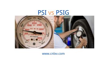
PSI vs PSIG: Difference Between
Source: Adobe Stock

PSI vs PSIG

PSI and PSIG are both units of pressure measurement.PSI measures absolute pressure, including atmospheric pressure, while PSIG measures pressure relative to atmospheric pressure, i.e. gauge pressure. When using valves, understanding the difference between PSI and PSIG can help in the proper selection and application of valves to ensure the safety and efficiency of your system.

Feature PSI PSIG
Definition Measure of pressure relative to a vacuum. Measure of pressure relative to ambient atmospheric pressure.
Reference Point Absolute vacuum (0 PSI absolute). Local atmospheric pressure (0 PSIG).
Usage Used in scientific contexts where absolute pressure is important. Commonly used in industrial and everyday applications where pressure is measured relative to ambient pressure.
Notation PSI or PSIA (Pounds per Square Inch Absolute). PSIG or psi(g).
Atmospheric Pressure Inclusion Includes atmospheric pressure (14.7 PSI at sea level). Excludes atmospheric pressure.
Typical Measurement Tools Absolute pressure gauges, barometers. Standard pressure gauges, tire pressure gauges.
Example Calculation A vacuum has 0 PSI absolute, whereas atmospheric pressure is 14.7 PSI absolute at sea level. A tire pressure reading of 30 PSIG means the pressure inside the tire is 30 PSI above atmospheric pressure.
Common Applications High precision scientific research, deep-sea diving, and space applications. Automotive tire pressure, HVAC systems, industrial processes.

Additional Details

  1. Absolute Pressure (PSI):
    • Absolute pressure is measured relative to the absolute vacuum (zero pressure).
    • It accounts for atmospheric pressure, which is approximately 14.7 PSI at sea level.
    • Example: A reading of 30 PSI absolute means the pressure is 30 PSI above the vacuum (absolute zero pressure).
  2. Gauge Pressure (PSIG):
    • Gauge pressure measures the pressure relative to the current atmospheric pressure.
    • It does not include atmospheric pressure in its measurement.
    • Example: A reading of 30 PSIG means the pressure is 30 PSI above the current atmospheric pressure.

Conversion between PSI and PSIG

  • To convert PSIG to PSI:
    PSI=PSIG+Atmospheric Pressure

    Atmospheric pressure is typically 14.7 PSI at sea level.

  • To convert PSI to PSIG:
    PSIG=PSI−Atmospheric Pressure

Example Calculation:

  • If a tire pressure gauge reads 30 PSIG, the absolute pressure inside the tire is:
    PSI=30 PSIG+14.7 PSI=44.7 PSI (absolute)
  • If the absolute pressure is 44.7 PSI, the gauge pressure is:
    PSIG=44.7 PSI−14.7 PSI=30 PSIG


PSIG vs. PSI and Valves

In the context of valves, understanding the distinction between PSI and PSIG is crucial for selecting the appropriate valve type and ensuring safe operation.

  1. Pressure Ratings: Valves are often rated in terms of their maximum pressure capacity. These ratings can be specified in either PSI or PSIG. It’s important to know which unit is being used to ensure the valve can handle the required pressure conditions.
  2. Application Suitability: Certain applications may require valves rated in PSIG due to the need for accurate pressure control relative to atmospheric conditions. For instance, in gas distribution systems, using PSIG-rated valves ensures that pressure readings account for atmospheric variations.
  3. Safety Considerations: Using the correct pressure unit helps prevent over-pressurization, which can lead to valve failure and safety hazards. Valves designed for PSIG measurements provide a safety buffer by accounting for atmospheric pressure, reducing the risk of accidental over-pressurization.


FAQs

Q1: Why is PSIG more commonly used than PSI in some industries?

A1: PSIG is preferred in industries where pressure variations relative to atmospheric pressure are critical. It provides a more accurate and relevant measure for applications like HVAC systems and industrial processes.

Q2: Can I convert PSI to PSIG?

A2: Yes, you can convert PSI to PSIG by subtracting the atmospheric pressure (approximately 14.7 PSI at sea level) from the PSI value. For example, if you have a PSI reading of 30, the PSIG would be 30 – 14.7 = 15.3 PSIG.

Q3: Are there any scenarios where PSI is more useful than PSIG?

A3: PSI is useful in scenarios where absolute pressure measurements are needed, such as in vacuum systems or when measuring pressure in environments with varying atmospheric conditions.

Q4: How do I determine the pressure rating of a valve?

A4: The pressure rating of a valve is usually indicated on the valve body or in the manufacturer’s specifications. It’s important to check whether the rating is in PSI or PSIG to ensure compatibility with your system’s requirements.

Q5: What happens if I use a valve with an incorrect pressure rating?

A5: Using a valve with an incorrect pressure rating can lead to over-pressurization, which may cause valve failure, leaks, or even catastrophic system failures. Always verify the pressure rating to ensure safe and efficient operation.


Conclusion

Understanding the difference between PSI and PSIG is essential for various industries to ensure accurate pressure measurements and safe system operations. While PSI measures absolute pressure, PSIG provides a gauge pressure reading relative to atmospheric pressure. This distinction is particularly important in applications involving valves, where the correct pressure rating ensures safe and efficient performance. By choosing the appropriate pressure unit and ensuring the correct valve specifications, industries can maintain optimal operations and safety standards.


Want To Explore More?

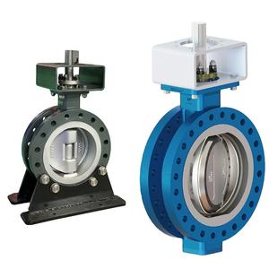
Best 10 Triple Offset Butterfly Valve Manufacturers in the World

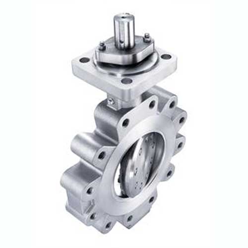
What Is Triple Offset Butterfly Valve?

Triple Offset Butterfly Valve, also known as Triple Offset Hard Seal Butterfly Valve, is an advanced butterfly valve design that is widely used in industrial and commercial applications. It achieves efficient sealing and low-torque operation through a triple eccentric structure. The design principle of triple eccentric butterfly valve is to deviate the contact surface between the butterfly plate and the valve seat from the center axis, so that the sealing surface no longer rubs when the valve is closed, which reduces wear and prolongs service life.


Triple Offset Butterfly Valve Manufacturers
Click Here → Triple Offset Butterfly Valve

Benefits Of Triple Offset Butterfly Valve

Triple offset butterfly valve has excellent sealing performance. Its triple eccentric design ensures that the valve is completely leak-free when closed, and maintains excellent sealing effect even under high pressure and high temperature conditions, which complies with API 607 and API 6FA fire test standards and guarantees the safety and reliability of the system.

Triple offset butterfly valves are extremely durable. Since its sealing surface is metal-to-metal contact, it reduces friction and wear, making the service life of the valve significantly longer. In addition, this design can effectively prevent the medium from erosion and corrosion of the sealing surface, which improves the adaptability of the valve in harsh working conditions.

Three offset butterfly valve has flexible operation and low energy consumption. As the unique design reduces the friction during opening and closing, the operating torque is smaller, thus reducing the energy consumption and maintenance cost of the actuator.

Triple Offset Butterfly Valve has a wide range of applicability. It is not only suitable for conventional water, steam and oil and gas media, but can also handle fluids containing solid particles, meeting the needs of various complex working conditions.


How Does A Triple Offset Butterfly Valve Work?

The design of the Triple Offset Butterfly Valve is characterized by three eccentric (offset) positions between the valve plate and the valve seat, which ensures that the valve will not cause friction during opening and closing, prolonging service life and providing better sealing performance.

The first offset is the centerline deviation of the valve stem relative to the valve seat. This design avoids direct friction between the valve plate and the seat during opening and closing, resulting in smoother operation while reducing wear and torque requirements.

The Second Offset is where the sealing surface of the valve plate is offset from the centerline of the valve stem. This eccentric design allows the valve plate to quickly disengage from the seat during opening, reducing wear and operating resistance. This off-center position helps to achieve rapid opening and closing of the valve.

The Third Offset is a geometrical deviation between the seat surface and the sealing surface of the valve plate. This design allows the valve plate to move closer to the seat during the closing process until a tight metal-to-metal contact is achieved, resulting in a zero-leakage seal. The position of the third eccentric ensures that the valve can still maintain good sealing performance under extreme conditions such as high temperature and high pressure.

The working principle of the triple offset butterfly valve is based on the precise design and manufacture of the three eccentric positions mentioned above. During operation, the valve plate controls the flow of fluid by rotating 90 degrees. When the valve opens, the valve plate quickly leaves the valve seat, avoiding friction and wear; when the valve closes, the valve plate gradually moves closer to the valve seat, ultimately forming a tight metal-to-metal seal. This design not only improves the durability of the valve, but also provides excellent performance in harsh environments such as high pressure, high temperature and corrosive media.


Top 10 Triple Offset Butterfly Valve Manufacturers

Here is an introduction to the top 10 Triple Offset Butterfly Valve Manufacturers:

1. Lixin Valve

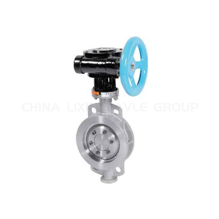
Lixin Valve is a renowned manufacturer in the industry, known for its high-quality, reliable, and innovative designs. The company’s products are widely used in industries such as oil, gas, chemical, power, and water treatment. Lixin Valve’s triple offset butterfly valves are noted for their exceptional sealing performance and durability, capable of maintaining stable operation under extreme conditions. Lixin Valve offers customized solutions to meet specific customer requirements and provides comprehensive after-sales service and technical support.


Butt Weld Butterfly Valve China Manufacturer
Click Here → Butt Weld Butterfly Valve

2. Emerson

Emerson is a global leader in automation and industrial solutions, with triple offset butterfly valves that excel in high-temperature and high-pressure environments. Emerson’s products feature excellent sealing performance and corrosion resistance, making them widely used in the oil, gas, and chemical industries. Emerson provides end-to-end services, from product selection to installation and commissioning, as well as maintenance and support, ensuring customers have peace of mind.


Triple Offset Valve Manufacturer
Source: Emerson

3. Cameron (Schlumberger)

Cameron, a subsidiary of Schlumberger, focuses on providing advanced fluid control solutions for the oil and gas industry. Its triple offset butterfly valves are known for their high reliability and long lifespan, suitable for harsh operating conditions. Cameron offers a wide range of products to meet various process requirements and provides global technical support and after-sales service.


Stainless Steel Triple Offset Butterfly Valves
Source: IndiaMart

4. Flowserve

Flowserve is a leading company in the fluid control field, and its triple offset butterfly valves are highly popular in the energy and industrial markets. Flowserve’s products are characterized by high efficiency and low maintenance costs, suitable for various complex operating conditions. The company is committed to providing the best solutions to customers through innovation and technological advancements, along with comprehensive training and support services.


Wholesale triple offset butterfly valve To Control Flow Of Gases And Liquids
Source: Alibaba

5. Crane Co.

Crane Co. is an industrial product manufacturer with a rich history, and its triple offset butterfly valves are widely used in the oil, chemical, and power industries. Crane’s products are well-designed and perform exceptionally well, with outstanding wear and corrosion resistance. Crane provides comprehensive customer support, from product selection to after-sales service, ensuring customers have the best user experience.


Triple Offset Butterfly Valves
Source: Crane

6. KOSO

KOSO is a well-known Japanese control valve manufacturer, and its triple offset butterfly valves perform excellently in demanding industrial applications. KOSO’s products are known for precise control and high reliability, widely used in chemical, petrochemical, and power industries. KOSO offers customized solutions and has a strong technical support team to ensure the best performance of products under various conditions.


Eccentric Butterfly Valves at best price
Source: KOSO

7. Bray International

Bray International is a leading global supplier of valves and control systems, with triple offset butterfly valves that perform well in various industrial applications. Bray’s products feature high efficiency and low leakage rates, suitable for harsh operating environments. The company is committed to continuous innovation to provide high-quality products and services to customers, supported by a global network of support and service.


Triple Offset Butterfly Valves: Tri Lok
Source: Bray

8. Hobbs Valve

Hobbs Valve specializes in the research and manufacture of high-performance triple offset butterfly valves, known for their exceptional sealing performance and reliability. Hobbs Valve’s products are widely used in the oil, gas, chemical, and power industries, capable of maintaining stable operation under extreme conditions. The company provides comprehensive technical support and after-sales service to ensure customers’ equipment is always in optimal condition.

Triple Offset Butterfly Valves at Rs 25000/unit

9. ADAMS Armaturen

ADAMS Armaturen is a renowned German valve manufacturer, and its triple offset butterfly valves perform excellently in high-temperature and high-pressure applications. ADAMS’ products are well-designed, with excellent durability and sealing performance, widely used in the power and petrochemical industries. The company provides professional technical support and after-sales service to ensure customers have the best product experience.


Triple Offset Butterfly Valves at Rs 11443/piece

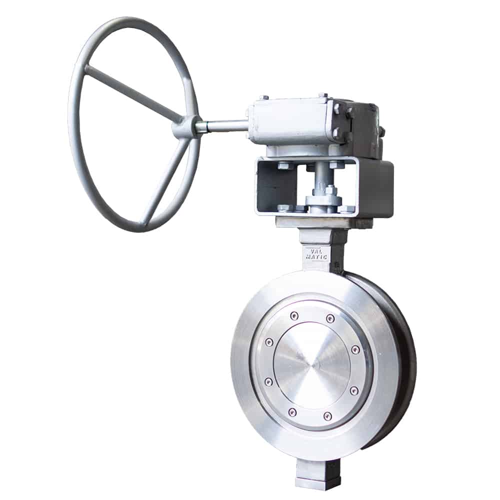
10. Val-Matic Valve & Manufacturing

Val-Matic is a well-known American valve manufacturer, and its triple offset butterfly valves are highly regarded in water treatment and industrial applications. Val-Matic’s products are characterized by high efficiency and long lifespan, suitable for various complex operating conditions. The company is committed to continuous improvement and innovation to provide high-quality products and services to customers, supported by comprehensive technical support and after-sales service.


Triple Offset Butterfly Valve
Source: Valmatic


These top triple offset butterfly valve manufacturers have secured significant positions in the global market through continuous innovation and by offering high-quality products and services. Their triple offset butterfly valves excel in various industrial applications, providing reliable fluid control solutions to customers.


FAQs

Q1: What are the differences between a triple offset butterfly valve and a traditional butterfly valve?

Triple offset butterfly valves have no friction during opening and closing, offering better sealing performance, making them suitable for more demanding conditions, while traditional butterfly valves are typically used for low-pressure, low-temperature environments.

Q2: Can a triple offset butterfly valve be used for bidirectional sealing?

Yes, a triple offset butterfly valve can achieve bidirectional sealing, ensuring effective sealing regardless of the direction of the flow.

Q3: How to select the appropriate material for a triple offset butterfly valve?

When selecting the material for a triple offset butterfly valve, consider the chemical properties, temperature, and pressure of the medium. Common materials include carbon steel, stainless steel, and alloy steel.

Q4: What standards do triple offset butterfly valves comply with?

Triple offset butterfly valves typically comply with international standards such as API 609, ISO 10631, and EN 593, ensuring quality and performance.

Q5: What is the temperature and pressure range of a triple offset butterfly valve? Triple offset butterfly valves can typically withstand high-temperature and high-pressure conditions. The specific temperature and pressure range depends on the valve material and design specifications, generally up to 800°F (427°C) and 2500 PSI.


Want To Learn More? Click Here To View Product Details!

Refinery Equipment: The Core Technology of Modern Refineries

The Importance of Oil Refinery

Oil Refinery plays an important role in the petroleum industry. Modern refineries convert crude oil into a variety of valuable products such as gasoline, diesel, jet fuel and lubricants through complex chemical and physical processes.

The refining process consists primarily of the steps of distillation, cracking, reforming and desulfurization. Crude oil is first passed through distillation towers for initial separation, and then through the cracking process to break up large molecules and produce lighter products. The reforming process further enhances product quality, while the desulfurization process removes harmful impurities.

Oil refinery equipment includes distillation columns, reactors, heat exchangers and storage tanks, each of which plays an important role in the refining process. As environmental awareness grows, refineries are moving toward going green, adopting cleaner technologies and equipment, such as hydrogen energy and carbon capture, to reduce pollutant emissions and carbon footprints. Going green not only improves productivity, but also promotes sustainable energy use, providing a win-win solution for both environmental protection and economic development.


Oil Refinery Equipment
Source: Adobe Stock

The History of Oil Refinery

The history of oil refining dates back to ancient times, but modern refining technology began in the mid-19th century.In 1859, Edwin Drake of the United States successfully drilled the first oil well in the modern sense in Pennsylvania, marking the beginning of the oil industry. Initially, oil was mainly used to produce kerosene to replace whale oil as a lighting fuel. However, with the invention of the internal combustion engine and the rise of the automobile industry, the demand for products such as gasoline and diesel fuel increased rapidly.

Early refineries were poorly equipped and mainly used simple distillation to separate crude oil into different fractions. in the early 20th century, with the development of chemical engineering and catalytic technology, new technologies such as catalytic cracking and catalytic reforming were introduced, which greatly improved refining efficiency and product quality. During World War II, the demand for synthetic fuels and high-octane gasoline drove further advances in refining technology.

In the 21st century, environmental protection and energy security issues have become important challenges for the refining industry. Modern refineries not only need to produce high quality fuels, but also need to reduce pollutant emissions and improve energy efficiency. The application of advanced catalysts, new separation technologies, as well as digital and automated control systems make the refining process more efficient and environmentally friendly.


Oil and Gas Refinery
Source: Adobe Stock

The Operation Process of Oil Refinery

The operation process of oil refinery includes the following main steps: First, crude oil is transported to the refinery through pipelines or tankers. Next, the crude oil undergoes pre-treatment to remove salts, water, and impurities, then enters the atmospheric distillation column for initial separation, producing naphtha, diesel, and heavy oil. The next step is further processing these initial products: naphtha undergoes catalytic reforming to generate high-octane gasoline and aromatics, while diesel and heavy oil are converted into lighter oil products through hydrocracking and catalytic cracking. Finally, the various finished products are subjected to blending, desulfurization, and denitrification processes to meet quality standards before storage and transportation.

Oil Refinery Operation Process Table

Step Main Process Products
Crude Oil Pre-treatment Desalting, Dehydration, Impurity Removal Purified Crude Oil
Atmospheric Distillation Distillation Separation Naphtha, Diesel, Heavy Oil
Catalytic Reforming Catalytic Reforming High-Octane Gasoline, Aromatics
Hydrocracking Hydrocracking Light Oil Products
Catalytic Cracking Catalytic Cracking Light Oil Products
Refining Blending, Desulfurization, Denitrification Qualified Finished Oil
Storage and Transportation Storage, Transportation Finished Oil

What Equipment is Necessary for a Large Oil Refinery?

Large oil refinery requires complex equipment to process and convert crude oil into a variety of petroleum products. This oil refinery equipment includes crude oil distillation towers, hydrogenation units, cracking units, desulfurization units, hydrocracking units, catalytic cracking units, reforming units, sulfur recovery units, and exhaust gas treatment systems.

First, the crude oil distillation tower is the core equipment of the refinery, which separates crude oil into fractions with different boiling point ranges through heating and distillation. Next come the hydrogenation units and hydrocrackers, which use hydrogen to convert heavy oils into lighter, more valuable products and remove impurities such as sulfur and nitrogen. Catalytic cracking units and reformers are used to further process these fractions to produce gasoline, diesel and other petrochemical products.

Desulfurization units and sulfur recovery units are environmentally friendly equipment designed to reduce sulfur emissions from the refining process. The desulfurization unit removes sulfur compounds from crude oil through a chemical reaction, while the sulfur recovery unit converts these sulfur compounds into a saleable sulfur product. In addition, exhaust treatment systems reduce harmful emissions through filtration and chemical treatment to ensure compliance with environmental regulations.

In addition, large oil refineries require a range of auxiliary equipment and facilities, such as heat exchangers, boilers, compressors, pumps, storage tanks, piping systems and automated control systems. This equipment ensures efficient, safe and continuous operation of the refining process.


Oil and gas industrial refinery at twilight, Oil refinery and Petrochemical plant pipeline steel, Refinery factory oil storage tank and pipeline steel at night.
Source: Adobe Stock

The Importance of Using Oil Refinery Equipment

Oil refinery equipment can effectively improve the utilization of crude oil. Through a series of complex chemical and physical processes, these equipments convert crude oil into a variety of valuable petroleum products, such as gasoline, diesel, lubricants and petrochemicals, minimizing waste and enhancing economic efficiency.

Oil refinery equipmenthelps to improve product quality and safety. Advances in modern refining technology enable the equipment to control reaction conditions more precisely, thus producing high-purity, high-quality products. This not only meets the market demand for high-quality petroleum products, but also improves the safety of the products and reduces the risks in the use process.

The use of advanced oil refinery equipment also significantly reduces environmental pollution. Modern equipment is usually equipped with a variety of environmental protection facilities, such as exhaust gas treatment systems and wastewater treatment devices, which can effectively reduce the emission of pollutants generated during the refining process and protect the environment.

The automation and intelligent development of oil refinery equipment has also greatly improved production efficiency and operational safety. Automated equipment reduces human errors in operation, and intelligent systems can monitor and adjust production parameters in real time to ensure that the equipment operates in the best condition.


Green Refining and Sustainable Development

Green refining and sustainable development is an important direction of current social development. Green refining technology realizes a win-win situation for both environmental protection and economic benefits by reducing energy consumption and waste emissions and improving resource utilization efficiency. It includes measures such as the use of renewable energy, the development of low-carbon emission processes and the recycling of waste to reduce the negative impact on the environment. Sustainable development emphasizes meeting the needs of the present without compromising the ability of future generations to meet their needs. By advancing green refining technologies and promoting the coordinated development of the economy, society and the environment, we can not only meet the challenges of resource depletion and environmental pollution, but also promote economic growth and realize the harmonious coexistence of man and nature.


Green Oil Refining
Source: Adobe Stock

FAQs

Q1:What are the main components of oil refinery equipment?

The main components include distillation columns, heaters, reactors, heat exchangers, pumps, pipelines, and control systems. Each component has specific functions such as separation, heating, reaction, and transfer.

Q2: How much does oil refinery equipment cost?

The cost of oil refinery equipment varies widely depending on the size and complexity of the refinery. A small, simple refinery might cost tens of millions of dollars, while a large, complex refinery can cost several billion dollars. Factors such as the type of crude oil processed, the range of products produced, and environmental regulations also impact the overall cost.

Q3: How do I choose the right oil refinery equipment?

Selecting the right equipment involves considering multiple factors, including the type of crude oil, the desired refined products, production capacity, technical parameters of the equipment, energy efficiency, and cost. It is usually necessary to have detailed discussions and planning with equipment suppliers or professional engineers.

Q4: What are the main safety hazards in the oil refining process?

Major safety hazards include high temperature and high-pressure operations, leaks of flammable and explosive substances, emissions of harmful gases, and equipment failures leading to fires and explosions. Strict adherence to safety operating procedures, regular safety inspections and training, and ensuring emergency response measures are in place are crucial.

Q5: How important are environmental protection measures in the oil refining process?

Environmental protection measures are very important, including the treatment and control of emissions, wastewater, and solid waste. Advanced environmental technologies and equipment should be used to minimize the environmental impact of the refining process, and compliance with relevant environmental laws and regulations is essential.


Want To Learn More?

Control Valve Should Always Be In What Position?

Valve Control

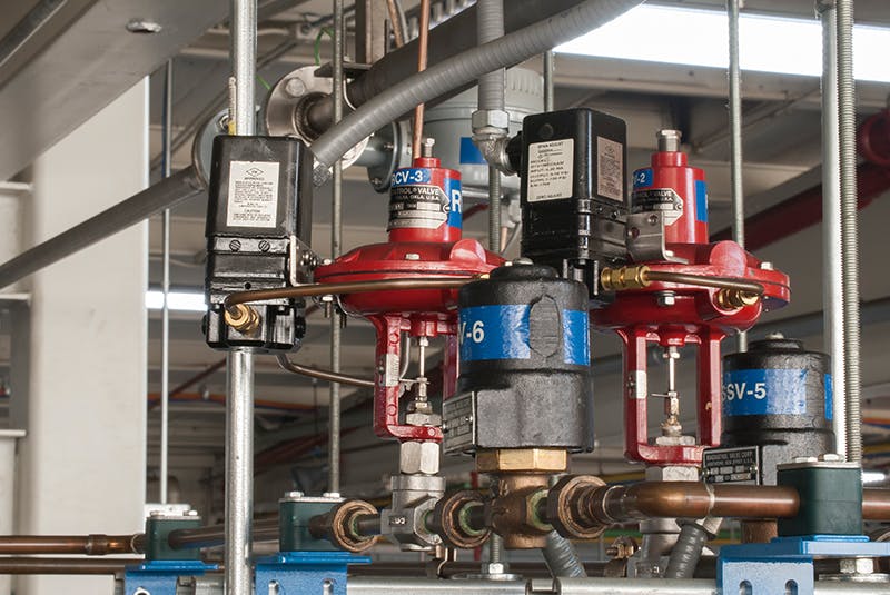
Valve control is a key component in industrial automation, ensuring the safety, efficiency and stability of the production process. By accurately controlling the switching state and flow rate of valves, the fluid flow rate, pressure and temperature can be regulated, thus optimizing the process parameters and improving the production efficiency. Modern valve control system usually adopts advanced sensors and actuators, and combines PLC, DCS and other automation control systems to realize all-round intelligent control and monitoring.

Valve control has a wide range of applications, covering a variety of industries such as petroleum, chemical, electric power, water treatment and so on. In the oil and gas industry, valve control is used to regulate the flow of oil pipelines to ensure transportation safety and energy utilization. In the chemical industry, precise valve control can realize the stability of pressure and temperature in the reactor and improve product quality. In the power industry, valve control is used to regulate steam flow in boilers and turbines to ensure stable operation of power plants. In the water treatment industry, valve control is used to regulate the flow of incoming and outgoing water to ensure the efficient operation of water treatment equipment.

With the development of Industry 4.0, valve control technology is also advancing, and the application of smart valves and remote control systems is becoming more and more popular. These innovative technologies not only improve the degree of automation of the production process, but also enhance the flexibility and responsiveness of the system, making industrial production safer, more environmentally friendly and efficient.


What Is a Control Valve?


what is a control valve
Source: ProcessingMagazine


A control valve is a device used to regulate the flow, pressure or temperature of a fluid, and is widely used in industrial and civil fields. It controls the passage of fluid by changing the position of the spool to achieve the purpose of regulation. Control valves are usually composed of an actuator and a valve body, the actuator can be electric, pneumatic or hydraulic, while the valve body is made of different materials, such as stainless steel, cast iron, copper, etc., according to the nature of the fluid and the working environment.

The working principle of the control valve mainly depends on the actuator to receive the control signal, drive the spool to move in the valve body, thus changing the flow cross-section area and realizing the precise control of the flow. For example, in a chemical production process, control valves can regulate the feed flow of the reactor to ensure stable reaction conditions. In addition, control valves can be used in temperature control systems to keep the temperature of the system within a set range by regulating the flow of hot water or steam.


Types Of Control Valves

When discussing “Control Valve Should Always Be In What Position”, it is important to understand that different types of control valves are suitable for specific locations and applications due to differences in their characteristics and functions.

Control Valve Type Characteristics Applications
Ball Valve Simple structure, easy operation, high pressure resistance, good sealing Oil, natural gas, chemical, water treatment
Butterfly Valve Compact structure, lightweight, quick opening and closing, good flow regulation Water treatment, HVAC systems, food and beverage, pharmaceuticals
Gate Valve Low fluid resistance, good sealing performance, suitable for fully open or fully closed state Water treatment, power plants, petrochemical, pharmaceuticals
Globe Valve Precise flow regulation, good sealing performance, suitable for high pressure and high temperature Oil, chemical, power plants, pharmaceuticals
Control Valve High control accuracy, suitable for automatic control systems Chemical, oil, natural gas, power plants
Solenoid Valve Quick opening and closing, simple structure, suitable for remote control Water treatment, pharmaceuticals, food and beverage, chemical
Plug Valve Good sealing performance, wear-resistant, suitable for high pressure and high temperature Chemical, oil, natural gas, power plants
Check Valve Prevents backflow of the medium, simple structure, easy maintenance Oil, chemical, water treatment, HVAC
Pressure Reducing Valve Regulates downstream pressure, maintains stable pressure output Water treatment, steam systems, air compressor systems
Steam Trap Valve Automatically discharges condensate, prevents steam leakage Steam systems, boilers, chemical equipment
Plug Valve Simple structure, easy operation, suitable for quick opening and closing Oil, natural gas, chemical, food and beverage
Diaphragm Valve Suitable for corrosive media, simple structure, easy to clean Pharmaceuticals, food and beverage, water treatment, chemical
Safety Valve Prevents system overpressure, automatic pressure relief protection Boilers, pressure vessels, chemical equipment, pipeline systems
Balancing Valve Regulates system flow, balances system pressure HVAC systems, hot water systems, refrigeration systems
Air Release Valve Removes air from the pipeline, prevents air blockages Water treatment, water supply systems, HVAC


Control Valves Should Always Be In The What Position?

The default position of a control valve is usually “normally closed” or “normally open”. Normally closed valves remain closed when there is no external signal, while normally open valves remain open when there is no external signal. The choice of default state depends on the design requirements of the system and safety considerations. For example, in applications where safety is paramount, such as emergency shutdown systems, normally closed valves are able to close automatically in the event of a system failure, preventing a hazardous situation from occurring.

During normal operation, the position of the control valve should be adjusted according to the actual needs of the system. The operator can send signals through the control system to adjust the opening of the valve to achieve precise control of flow, pressure or temperature. This real-time adjustability allows the control valve to adapt to changing operating conditions and ensures stable system operation.

Regular maintenance and inspection are also key to ensuring that control valves are always in the correct position. The operational status and performance of control valves can change over time, so regular inspections and maintenance are required to ensure their sensitivity and reliability. During maintenance, operators should scrutinize the valve’s sealing, responsiveness, and on/off status to identify and resolve potential problems in a timely manner.

Another important factor to pay attention to is the setting of the control system. The control system should be able to accurately monitor and regulate the position of the control valve and respond to changes in external signals in a timely manner. When designing and installing the control system, it should be ensured that it has sufficient sensitivity and stability to work reliably under different operating conditions.

The optimal position of different types of control valves for specific applications can vary. For example, control valves are usually used for precise flow control, so their openings should be dynamically adjusted according to actual demand. In some special applications, such as pressure relief valves or safety valves, their position and switching status need to be specially designed and set to ensure that pressure can be quickly released when the system is overpressurized to protect equipment and personnel.


FAQs On Control Valves

Q1: What is the function of a control valve?

The function of a control valve is to regulate the flow of a fluid (liquid or gas) by varying the size of the flow passage. This allows for precise control of process parameters such as flow rate, pressure, temperature, and liquid level in various industrial systems.

Q2: What are the three basic control valves?

The three basic types of control valves are:

  1. Globe Valve: Known for precise control and good throttling capability, used in applications where accurate flow control is required.
  2. Ball Valve: Offers quick shutoff and is used in applications requiring a tight seal and where a full-flow path is necessary.
  3. Butterfly Valve: Provides good control and is suitable for large flow rates in low-pressure applications due to its simple and compact design.

Q3: How do positioners enhance control valve performance?

Positioners are devices that ensure the valve actuator reaches the desired position by comparing the control signal to the actual valve position and making adjustments as needed. They improve the accuracy, responsiveness, and stability of the control valve, especially in applications requiring precise control or where there is significant friction or deadband in the valve mechanism.

Q4: What is the role of a control valve in a PID control loop?

In a PID (Proportional, Integral, Derivative) control loop, the control valve acts as the final control element that adjusts the flow or pressure based on the output signal from the PID controller. The PID controller processes the difference between the setpoint and the process variable, sending the appropriate signal to the control valve to achieve the desired control objective.

Q5: What is cavitation and how does it affect control valves?

Cavitation occurs when the pressure in a liquid drops below its vapor pressure, causing the formation of vapor bubbles. These bubbles collapse violently when they reach a region of higher pressure, creating shock waves that can damage valve components. Cavitation can lead to noise, vibration, erosion, and premature valve failure.


Want To Learn More? Click Here To View Product Details!

API 600 vs API 602

What is API 600?

API 600 Gate Valve
Click Here → API 600 Gate Valve

API 600 Standard

API 600 is known as the “Steel Gate Valve Design and Manufacturing Specification.” This standard applies to steel gate valves used in petroleum, natural gas, and related industries, covering the following key aspects:

Design Requirements: API 600 specifies the design criteria for steel gate valves, including structural strength, sealing performance, and corrosion resistance. These requirements ensure that valves can operate reliably in high-pressure and high-temperature environments.

Manufacturing Requirements: API 600 details manufacturing processes, material selection and quality control for valves. Critical components such as valve bodies, bonnets, stems and seats must be constructed of approved materials and go through a rigorous manufacturing process to ensure performance.

Testing and Inspection: In accordance with API 600 standards, valves must pass rigorous testing and inspection before leaving the factory. These tests include pressure tests, leakage tests and visual inspections to ensure that the valves are free of defects and safe to operate.

API 600 valves are typically used in large-diameter, high-pressure, and high-temperature applications, such as refineries, chemical plants, and natural gas processing facilities.


What is API 602?


API 602 Forged Gate Valve
Click Here → API 602 Forged Gate Valve

API 602 Standard

API 602 is known as the “Compact Steel Gate Valves and Plug Valves for Refinery Use.” This standard is applicable to small-diameter forged steel gate valves and plug valves, focusing on the following areas:

Design Requirements: API 602 outlines the design standards for forged steel gate valves and plug valves, emphasizing compactness and ease of operation compared to API 600.

The design must ensure effective sealing and stable operation in high-pressure and high-temperature environments.

Manufacturing Requirements: API 602 specifies the materials and manufacturing processes for forged steel valves. These valves must be made from high-strength, high-toughness materials to withstand demanding conditions.

Testing and Inspection: API 602 specifies that a comprehensive testing and inspection program, including pressure and leakage tests, must be performed. These tests are designed to ensure the safe and reliable operation of the valve in actual use.

API 602 valves are suitable for small-diameter, high-pressure, and high-temperature applications such as pipeline systems and high-pressure boilers. These valves are valued for their compact design, robustness, and ease of operation.


API 600 vs API 602

API 600 vs API 602 Gate Valve
Source: Lixin

API 600 and API 602 are both standards set by the American Petroleum Institute (API) for gate valves, but they differ in several key aspects. Below is a detailed comparison based on design differences, temperature rating changes, differences in sealing elements, and differences in application scope.


Design Differences

API 600:

  • Type: Bolted bonnet steel gate valves.
  • Size Range: Typically 2 inches and larger.
  • Pressure Ratings: Class 150 to 2500.
  • Construction: Heavy wall thickness to handle higher pressures and temperatures.
  • Body Materials: Usually carbon steel, alloy steel, stainless steel.

API 602:

  • Type: Compact steel gate valves.
  • Size Range: Generally 4 inches and smaller.
  • Pressure Ratings: Class 150 to 1500.
  • Construction: Compact design for lower weight and smaller installation footprint.
  • Body Materials: Carbon steel, alloy steel, stainless steel.


Temperature Rating Changes

API 600:

  • Designed for high-temperature applications with a wide range of operating temperatures.
  • Suitable for temperatures up to approximately 593°C (1100°F) depending on the material used.

API 602:

  • Suitable for moderate temperature applications.
  • Typically designed for temperatures up to approximately 427°C (800°F) depending on the material used.


Differences in Sealing Elements

API 600:

  • Seating: Usually hard-faced with materials like Stellite for better wear resistance.
  • Stem Seals: Multiple types available, including packing options like graphite for high-temperature services.
  • Backseat: Provides additional sealing and packing replacement while under pressure.

API 602:

  • Seating: Often uses elastomeric or metallic seats depending on the application.
  • Stem Seals: Limited to fewer packing options compared to API 600, typically suited for lower temperature and pressure applications.
  • Backseat: May not always be available or necessary due to lower pressure ratings.


Differences in Application Scope

API 600:

  • Typically used in larger, high-pressure, and high-temperature applications like oil refineries, petrochemical plants, and power generation.
  • Suitable for critical applications where reliability and longevity are paramount.

API 602:

  • Ideal for smaller, moderate pressure and temperature applications.
  • Commonly used in utilities, small process applications, and where space and weight are a concern.


Comparison Table

Aspect API 600 API 602
Type Bolted bonnet steel gate valves Compact steel gate valves
Size Range 2 inches and larger 4 inches and smaller
Pressure Ratings Class 150 to 2500 Class 150 to 1500
Construction Heavy wall thickness Compact design
Body Materials Carbon, alloy, stainless steel Carbon, alloy, stainless steel
Temperature Range Up to 593°C (1100°F) Up to 427°C (800°F)
Seating Hard-faced (e.g., Stellite) Elastomeric or metallic
Stem Seals Multiple options including graphite Limited packing options
Backseat Yes Sometimes
Application Scope Large, high-pressure, high-temp Refineries, petrochemical, power Small, moderate pressure/temp Utilities, small process


FAQs on API 600 & API 602

Q1: Can API 602 valves be used in high-temperature applications?

  • A: API 602 valves are typically designed for moderate temperatures. For high-temperature applications, API 600 valves are more suitable due to their construction and material specifications.

Q2: What are the key material differences between API 600 and API 602 valves?

  • A: API 600 valves use materials capable of withstanding higher pressures and temperatures, while API 602 valves use materials suitable for moderate conditions and compact designs.

Q3: Are API 600 valves more expensive than API 602 valves?

  • A: Generally, API 600 valves are more expensive due to their larger size, higher pressure rating, and use of more robust materials. API 602 valves, being smaller and designed for less demanding conditions, are typically less costly.

Q4: How do I choose between API 600 and API 602 valves for my application?

  • A: The choice depends on your specific application requirements, including pressure, temperature, space constraints, and industry standards. For high-pressure, high-temperature applications, API 600 is recommended. For compact, moderate conditions, API 602 is more suitable.

Q5: Are there any alternative standards to API 600 and API 602?

  • A: Yes, other standards exist for gate valves depending on the application and region. Some examples include ASME B16.34, ISO 10434, and MSS SP-81. However, API 600 and 602 are widely recognized and utilized within the oil and gas industry.


Want To Learn More? Click Here To View Product Details!

API 607 vs API 608

Industrial environments dealing with flammable and combustible materials require stringent safety measures, especially concerning valve performance under fire conditions. This is where the American Petroleum Institute (API) standards, specifically API 607 and API 608, come into play. These standards provide a framework for testing and certifying valves for fire safety, ensuring their integrity in extreme situations.


What is API 607?


Standard API 607 Ball Valve
Source: IndiaMART


API 607 outlines the fire test requirements for quarter-turn valves with soft seats, commonly used in hydrocarbon processing, chemical plants, and other industries. The focus is on preventing internal leakage when the valve is subjected to a standardized fire test.


Key aspects of API 607

Scope: This standard applies to quarter-turn valves, including ball, plug, and butterfly valves, with soft seats made from elastomers or polymers.

Test Conditions: API 607 mandates a demanding fire test where the valve is exposed to a temperature of 1400°F (760°C) for 30 minutes. During the test, the valve is pressurized with a test medium, typically water or air, and leakage is carefully monitored.

Acceptance Criteria: To pass the API 607 fire test, the valve must demonstrate minimal internal leakage through the seat and stem during and after the fire exposure. The standard defines specific permissible leakage rates.

What is API 608?

API 608 Ball Valve
Source: Lixin


While API 607 covers a broader range of quarter-turn valves, API 608 specifically focuses on fire testing requirements for metal ball valves. This standard emphasizes both internal and external leakage during the fire test, making it stricter in its assessment. API 608 Ball Valve


Key aspects of API 608

Test Conditions: Similar to API 607, the valve is subjected to a fire test at 1400°F (760°C) for 30 minutes. However, API 608 includes an additional requirement for external leakage testing.

Leakage Assessment: API 608 requires monitoring for both internal leakage through the seat and external leakage through the stem packing and body seals.

Acceptance Criteria: Passing the API 608 fire test requires adhering to more stringent leakage limits for both internal and external leakage compared to API 607.


API 607 vs API 608

Feature API 607 API 608
Scope Fire test standards for valve performance in fire conditions. Standards for design, inspection, and testing of metal-seated ball valves.
Valve Types Soft-sealed valves, e.g., ball and butterfly valves. Metal-seated ball valves, including cast and trunnion.
Purpose Enhance safety by ensuring valves can halt or control fluid flow in fire scenarios. Ensure valve performance under various pressure and temperature conditions.
Testing Conditions Simulates fire scenarios to test valve integrity and function. Tests under normal operating conditions to assess pressure handling and sealing.
Certification Requires valves to withstand direct flames and function post-test. Valves must meet specific operating pressures and temperatures post-testing.
Industry Application Used in industries where fire safety is critical, such as oil, gas, and chemicals. Primarily used in the oil and gas sector for fluid handling.
Testing Process Includes exposure to flames and thermal cycles. Involves rigorous pressure and sealing tests.
Design Focus Primarily on maintaining sealing properties during and after fire exposure. On durability and performance in varying operational conditions.

API 607 Fire Safe Test Procedure

The fire test procedure outlined in API 607 involves a series of well-defined steps:

Valve Preparation: The valve is prepared by removing any non-essential components and ensuring the sealing surfaces are clean and free from debris.

Test Setup: The valve is mounted in a dedicated test fixture and connected to a pressure source and a leakage collection system.

Initial Pressure Test: Before the fire test, the valve undergoes a preliminary pressure test to verify its initial integrity and sealing capacity.

Fire Exposure: The valve is then subjected to the standardized fire test using a furnace or a calibrated burner. The temperature is carefully controlled and monitored throughout the 30-minute exposure.

Leakage Monitoring: During and after the fire test, any internal leakage through the seat and stem is collected and measured.

Post-Test Inspection: After the fire test, the valve is visually inspected for any signs of damage, deformation, or deterioration.


API 608 Fire Safe Test Procedure

The API 608 fire test procedure follows a similar pattern to API 607, with additional steps for evaluating external leakage:

Valve Preparation: Similar to API 607, the valve is prepared by removing any non-essential components and ensuring clean sealing surfaces.

Test Setup: The valve is mounted in a test fixture, connected to a pressure source, and equipped with collection systems for both internal and external leakage.

Initial Pressure Test: An initial pressure test is performed to verify the valve’s integrity before the fire test.

Fire Exposure: The valve undergoes the standardized fire test at 1400°F (760°C) for 30 minutes.

Leakage Monitoring: Both internal and external leakage are meticulously monitored and measured throughout the test.

Post-Test Inspection: A thorough visual inspection is conducted to assess any damage or deformation caused by the fire exposure.


Significance of API 607 and API 608 in Industrial Safety

API 607 and API 608 play a vital role in ensuring the reliability and safety of valves in fire-prone environments. By adhering to these standards, manufacturers can demonstrate the fire-resistant capabilities of their valves, providing a higher level of assurance to plant operators and engineers. This peace of mind translates into increased operational safety, reduced risk of fire-related incidents, and compliance with industry best practices and regulatory requirements.


Benefits of Utilizing API 607/608 Certified Valves

Enhanced Safety: Choosing certified valves offers greater confidence in their fire-resistant capabilities, mitigating risks and safeguarding personnel.

Compliance with Industry Standards: Utilizing certified valves demonstrates adherence to recognized best practices and regulatory requirements.

Reduced Liability: Specifying compliant valves minimizes potential liabilities and legal issues associated with fire-related incidents.

Increased Operational Reliability: Fire-tested valves provide greater reliability and reduced risk of malfunctions during critical situations, ensuring process continuity.


FAQs on API 607 & API 608

Q: What does “fire-safe” mean in the context of API 607?

“Fire-safe” refers to the ability of valves to maintain their integrity and functionality even in the presence of fire or high-temperature conditions. Valves that comply with API 607 standards undergo rigorous testing to ensure they can withstand extreme heat and pressure, thereby preventing catastrophic failures during fire incidents.

Q: What are the key testing requirements outlined in API 607?

API 607 mandates various tests, including fire endurance testing, thermal cycling, and pressure testing, among others. These tests assess the valve’s performance under simulated fire conditions, ensuring it can effectively control fluid flow and maintain tight shut-off even when exposed to intense heat and pressure.

Q: What is the certification process for API 608?

API-certified manufacturers can produce valves that meet API 608 standards. The certification process includes submitting relevant documents and information, undergoing audits, and conducting on-site reviews and tests.

Q: What requirements does the API 608 standard have for valve quality?

API 608 stipulates the requirements for valve materials, dimensions, design pressure, sealing performance, operation methods, etc. to ensure the safety and reliability of valves in use.

Q: Do valves have to meet API 607 or API 608?

Not all valves need to comply with these standards. Typically, valves are required to meet API 607 or API 608 for applications where there is a high risk of fire or where stringent safety standards are required.


Want To Learn More? Click Here To View Product Details!

Quality Super Stainless Steel Plug Valves: Features & Benefits

As a professional in the field, I have run into many kinds of valves throughout the years. Amongst them, Quality Super Stainless steel Plug Valves stand apart as a result of their extraordinary characteristics. These valves are designed to give reputable and reliable flow control in numerous commercial applications. Here are some of the vital attributes that make these valves a preferred option:

Material Composition: Quality super stainless-steel plug valves are made from state-of-the-art stainless-steel, which supplies excellent resistance to corrosion, rust, and chemical damages. This guarantees durability and longevity, also in harsh settings.

Design and Construction: These valves include a structured body design that decreases pressure decrease and boosts circulation effectiveness. The plug device guarantees a tight seal, stopping leakages and maintaining constant performance.

Temperature Level and Pressure Ratings: Quality super stainless steel plug valves can dealing with a large range of temperatures and pressures. This makes them suitable for both low and high-pressure applications, in addition to for usage in extreme temperature level conditions.

Ease of Procedure: The style of these valves permits easy operation, with alternatives for manual, electrical, or pneumatically-driven actuation. This versatility makes sure that the valves can be incorporated seamlessly into numerous control systems.

Upkeep and Use: One of the standout attributes of these valves is their convenience of upkeep. The straightforward plug design permits fast disassembly and reassembly, decreasing downtime and maintenance prices.

Flexibility: These valves are offered in various dimensions, materials, and arrangements to satisfy the details needs of various applications. Whether used in chemical processing, oil and gas, or water treatment, they give dependable performance.

Key Points

  • Material Composition: High-grade stainless steel
  • Design and Construction: Streamlined body, tight seal
  • Temperature and Pressure Ratings: Wide range compatibility
  • Ease of Operation: Manual, electric, pneumatic
  • Maintenance and Use: Quick disassembly, reassembly
  • Flexibility: Available in various sizes, materials
Super Stainless Steel Plug Valves at Rs 1000
Source: IndiaMart

Attributes of Quality Super Stainless Steel Plug Valves

As a professional in the field, I have run into many kinds of valves throughout the years. Amongst them, Quality Super Stainless-steel Plug Valves stand apart as a result of their extraordinary characteristics. These valves are designed to give reputable and reliable flow control in numerous commercial applications. Here are some of the vital attributes that make these valves a preferred option:

Material Composition: Quality super stainless-steel plug valves are made from state-of-the-art stainless-steel, which supplies excellent resistance to corrosion, rust, and chemical damages. This guarantees durability and longevity, also in harsh settings.

Style and Construction: These valves include a structured body design that decreases pressure decrease and boosts circulation effectiveness. The plug device guarantees a tight seal, stopping leakages and maintaining constant performance.

Temperature Level and Pressure Ratings: Quality super stainless steel plug valves can dealing with a large range of temperatures and pressures. This makes them suitable for both low and high-pressure applications, in addition to for usage in extreme temperature level conditions.

Ease of Procedure: The style of these valves permits easy operation, with alternatives for manual, electrical, or pneumatically-driven actuation. This versatility makes sure that the valves can be incorporated seamlessly into numerous control systems.

Upkeep and Use: One of the standout attributes of these valves is their convenience of upkeep. The straightforward plug design permits fast disassembly and reassembly, decreasing downtime and maintenance prices.

Flexibility: These valves are offered in various dimensions, materials, and arrangements to satisfy the details needs of various applications. Whether used in chemical processing, oil and gas, or water treatment, they give dependable performance.

Feature Summary
Product Structure High-grade stainless-steel with excellent rust resistance
Design and Construction Streamlined body, limited seal, very little pressure decrease
Temperature Level and Stress Scores Appropriate for a large range of temperature levels and pressures
Alleviate of Procedure Guidebook, electric, or pneumatically-driven actuation choices
Maintenance and Use Quick disassembly and reassembly for lowered downtime
Flexibility Offered in various sizes, materials, and arrangements


Advantages of Utilizing Stainless Steel Plug Valves in Industrial Applications

Making use of stainless steel plug valves in industrial applications provides various advantages, making them a recommended option for lots of industries. One of the key benefits is their phenomenal rust resistance. Stainless-steel, by its nature, resists rust and rust much better than other materials, guaranteeing long-term sturdiness and dependability in extreme environments.

Another substantial advantage is their high toughness and durability. These valves are developed to stand up to high pressure and temperature level problems, making them ideal for demanding applications such as chemical processing, oil and gas, and power generation. The robust construction of quality super stainless steel plug valves guarantees they maintain their honesty under extreme conditions.

Stainless steel plug valves likewise supply exceptional flow control. Their style permits a tight shut-off, preventing leakage and ensuring effective operation. This precise control over the flow of fluids or gases is critical in keeping the security and performance of commercial procedures.

Additionally, these valves call for marginal maintenance. Due to their longevity and deterioration resistance, they have a longer solution life and need much less frequent servicing contrasted to valves made from various other products. This reduces downtime and upkeep prices, adding to overall operational efficiency.

Hygiene is an additional crucial advantage, specifically in sectors like food and beverage or drugs. The smooth surface of stainless-steel is easy to clean and does not nurture germs, making stainless-steel plug valves perfect for applications where hygienic problems are critical.

Last but not least, the flexibility of stainless steel plug valves can not be overemphasized. They are available in numerous types and setups, making them ideal for a large range of applications. Whether it’s a high-pressure or high-temperature atmosphere, there is a stainless steel plug valve developed to fulfill details commercial requirements.

Sorts Of Stainless Steel Plug Valves and Their Uses

When it pertains to quality super stainless-steel plug valves, recognizing the different kinds available and their certain uses is important for picking the appropriate valve for your application. Listed below, we lay out the key sorts of stainless steel plug valves and their regular uses in numerous industries.

Lubricated Plug valves

Lubricated plug valves function a dental caries in between the plug and the body, which is loaded with a lubricant in order to decrease rubbing and sealing wear. These valves are particularly valuable in applications entailing high stress and temperature, such as in the oil and gas sector.

Non-Lubricated Plug Valves

Non-lubricated plug valves utilize a sleeve or lining made from products like PTFE (Polytetrafluoroethylene) to achieve a tight seal without the requirement for lubrication. These valves are suitable for applications where contamination from lubricants should be avoided, such as in food and beverage processing or pharmaceutical sectors.

Multi Port Plug Valves

Multi port plug valves are developed with multiple ports, permitting the control of flow between a number of different paths. This makes them extremely efficient for intricate piping systems where space and price savings are important, such as in chemical handling plants.

Eccentric Plug valves

Eccentric plug valves function an off-center plug that minimizes wear and improves sealing capacities. These valves are particularly suited for managing slurries, sludge, and other thick fluids, making them preferred in wastewater treatment and slurry handling markets.

Expanding Plug valves

Expanding plug valves provide a tight, bi-directional seal that is maintained also under high-pressure conditions. These valves are generally made use of in applications needing isolation and accurate circulation control, such as in all-natural gas circulation and storage space systems.

Sort of Valve Secret Features Typical Applications
Lubricated Plug Valves High-pressure and temperature level resistance Oil and Gas
Non-Lubricated Plug valves Contamination-free securing Food and Drink, Pharmaceuticals
Multi Port Plug valves Control of numerous circulation pathways Chemical Handling
Eccentric Plug valves Minimized wear, enhanced securing Wastewater Therapy, Slurry Handling
Expanding Plug Valves Bi-directional securing under high pressure Natural Gas Circulation, Storage Space Equipments


Quality Super Stainless Steel Plug Valves
Source: FluoroSeal Group

Just how to Pick the Right Stainless Steel Plug Valve for Your Needs

When choosing a stainless steel plug valve for your application, a number of vital aspects require to be considered to make sure optimum efficiency and longevity. Below are key elements to keep in mind:

1. Material Top quality

The high quality of the stainless-steel made use of in the plug valve is paramount. Search for valves made from state-of-the-art stainless-steel such as 304 or 316, which supply outstanding deterioration resistance and sturdiness. Quality super stainless-steel plug valves often go through strenuous screening to satisfy market requirements.

2. Valve Dimension and Type

Establish the appropriate size and kind of valve for your specific application. Plug valves come in different sizes and styles, including lubricated, non-lubricated, and multi-port configurations. The dimension needs to match your pipeline diameter to make certain correct circulation control and reduce pressure drops.

3. Temperature and Pressure Scores

Think about the operating temperature level and stress conditions of your system. Stainless-steel plug valves need to be rated to take care of the optimum temperature level and stress they will certainly come across. Top notch valves are designed to maintain integrity and performance under severe conditions.

4. End Connections

End links are essential for compatibility with your existing pipeline system. Usual link types include threaded, flanged, and welded ends. Pick a valve with the proper connection type to ensure a secure and leak-free installation.

5. Flow Control Requirements

Assess your flow control requires, consisting of the called for flow price and the nature of the liquid being regulated. Plug valves are functional and can manage a selection of fluids, consisting of gases, liquids, and slurries. Make certain the valve you choose can handle your particular flow control requirements effectively.

6. Upkeep and Relieve of Operation

Take into consideration the upkeep demands and convenience of procedure of the valve. Premium stainless-steel plug valves are developed for reduced maintenance and very easy operation, with attributes such as a straightforward quarter-turn mechanism for fast opening and closing. Additionally, try to find valves with exchangeable elements to simplify maintenance jobs.

7. Compliance with Specifications

Guarantee that the plug valve adheres to appropriate market criteria and accreditations. valves that fulfill international standards, such as API, ANSI, and ISO, supply an assurance of high quality and integrity. This is especially important in crucial applications where security and performance are extremely important.

By meticulously thinking about these variables, you can pick the right stainless-steel plug valve that satisfies your particular demands and makes certain dependable and effective operation in your commercial applications.

Maintenance and Treatment Tips for Stainless Steel Plug Valves

Correct upkeep and treatment of stainless steel plug valves are critical to ensuring their durability and optimum efficiency. Right here are some crucial pointers to remember:

Regular Assessment

Conduct routine examinations to spot any kind of very early signs of wear or damage. Look for leakages, rust, and any kind of uncommon noises during operation. Early detection can stop a lot more considerable issues down the line.

Cleansing

Maintain the valves tidy from dust, particles, and chemical residues. Usage ideal cleaning agents that do not respond adversely with stainless-steel. Regular cleaning prevents build-up that can influence valve efficiency.

Lubrication

Lube moving components of the valve with appropriate lubricants to guarantee smooth operation. Prevent making use of lubricants that can cause corrosion or react with the media streaming with the valve.

Securing and Packing

Inspect the seals and packaging for damage. Change them as needed to keep a limited seal and stop leaks. Guarantee that the replacement parts are suitable with the details kind of stainless-steel plug valve being used.

Torque Settings

Follow the supplier’s recommended torque settings when tightening up screws and nuts. Over-tightening can create damages to the valve body or the sealing parts, while under-tightening can result in leaks.

Storage space

When not in use, keep the valves in a clean, completely dry location to stop corrosion and contamination. Cover completions of the valve to shut out dust and debris.

Expert Maintenance

Engage professional servicing at routine intervals. Professional technicians can supply a comprehensive assessment and upkeep that might not be feasible through routine checks.

Upkeep Job Regularity Information
Assessment Monthly Check for leakages, deterioration, and unusual noises.
Cleansing Quarterly Eliminate dirt, debris, and chemical deposits.
Lubrication Every 6 months Apply suitable lubricants to relocating components.
Securing and Loading Annually Replace used seals and packing.
Torque Settings As needed Ensure bolts and nuts are effectively tightened up.
Storage When not being used Shop in a clean, dry location.
Expert Servicing Yearly Thorough inspection and maintenance by specialists.


Leading Manufacturers of Quality Super Stainless Steel Plug Valves

When it involves quality super stainless steel plug valves, several makers attract attention due to their commitment to excellence, innovation, and dependability. These firms have developed a solid online reputation in the sector by constantly supplying items that fulfill stringent quality standards and accommodate diverse commercial demands.

1. Velan Inc.

. Velan Inc. is renowned for its high-performance stainless-steel plug valves. With an extensive item array, Velan gives valves made for resilience and efficiency in different industrial applications. Their items undertake extensive screening to guarantee they satisfy global requirements.

2. Flowserve Company

Flowserve Company is an international leader in the manufacture of circulation control items. Their stainless steel plug valves are extensively utilized in industries such as oil and gas, chemical handling, and power generation. Flowserve’s valves are recognized for their precision design and reliability.

3. Emerson Electric Co.

Emerson Electric Co. offers a vast range of stainless-steel plug valves under its numerous brands, consisting of Fisher and Virgo. These valves are created to offer phenomenal control and sturdiness, making them ideal for the most requiring industrial settings.

4. Crane Co.

Crane Co. is an additional prominent producer of quality super stainless steel plug valves. Their items are crafted to supply superior performance and longevity. Crane Co.’s commitment to technology ensures that their valves fulfill the developing requirements of modern-day sectors.

5. KITZ Firm

KITZ Firm, based in Japan, is recognized for its extensive series of stainless-steel plug valves. KITZ valves are acknowledged for their precision, dependability, and adherence to top notch requirements, making them a favored option in different commercial fields.

6. Bray International, Inc.

Bray International, Inc. concentrates on the style and manufacture of top quality stainless steel plug valves. Their items are made to offer robust efficiency and are widely used in markets such as water treatment, petrochemical, and mining.

Contrast Table

Supplier Secret Includes Industries Served
Velan Inc. . High-performance, extensive screening General Industrial, Oil & Gas
Flowserve Company Accuracy design, dependability Oil & Gas, Chemical Handling, Power Generation
Emerson Electric Co. . Outstanding control, toughness Various Industrial Applications
Crane Co. . Superior performance, longevity General Industrial, Specialized Applications
KITZ Company Precision, reliability, high-grade criteria General Industrial, Specialized Applications
Bray International, Inc. . Robust performance Water Treatment, Petrochemical, Mining

These leading makers make sure that their quality super stainless steel plug valves are made and produced to provide optimal efficiency, dependability, and longevity. By selecting items from these reliable companies, industries can be certain in the toughness and performance of their valve solutions.

FAQs about Quality Super Stainless Steel Plug Valves

What are the key features of Quality Super Stainless Steel Plug Valves?

Quality Super Stainless Steel Plug Valves are known for their material composition of high-grade stainless steel, streamlined design, wide temperature and pressure ratings, ease of operation, maintenance ease, and versatility in various applications.

What are the benefits of using Stainless Steel Plug Valves in industrial applications?

Stainless Steel Plug Valves offer exceptional corrosion resistance, high strength and toughness, excellent flow control, minimal maintenance requirements, hygiene benefits, and versatility for a wide range of applications.

What are the types of Stainless Steel Plug Valves and their uses?

The types of Stainless Steel Plug Valves include Lubricated Plug Valves, Non-Lubricated Plug Valves, Multi-Port Plug Valves, Eccentric Plug Valves, and Expanding Plug Valves, each serving specific purposes in industries like oil and gas, food and beverage, chemical processing, wastewater treatment, and natural gas distribution.

How can I choose the right Stainless Steel Plug Valve for my needs?

Consider factors such as material quality, valve size and type, temperature and pressure ratings, end connections, flow control requirements, maintenance and ease of operation, and compliance with industry standards when choosing the right Stainless Steel Plug Valve for your application.

What maintenance and care tips should I follow for Stainless Steel Plug Valves?

Regularly inspect the valves, keep them clean, lubricate moving parts, check and replace seals and packing, follow torque settings, store properly when not in use, and engage in professional servicing at regular intervals to ensure the longevity and optimal performance of Stainless Steel Plug Valves.

Who are some leading manufacturers of Quality Super Stainless Steel Plug Valves?

Leading manufacturers of Quality Super Stainless Steel Plug Valves include Velan Inc., Flowserve Corporation, Emerson Electric Co., Crane Co., KITZ Corporation, and Bray International, Inc., each offering high-quality valves designed for durability and reliability in various industrial applications.

API 6D Ball Valve: A Complete Guide

What is API 6D Ball Valve?


API 6D Ball Valve at best price
Source: IndiaMART


API 6D ball valves comply with American Petroleum Institute (API) standard 6D and are commonly used in oil and gas, chemical and other industrial fields. The ball valves offered by us fully comply with the design, manufacturing and testing standards of API 6D specifications. Ball valves are designed and manufactured to ensure maximum service life and reliability, and all valves comply with API 6D full bore or reduced bore requirements. We offer a full range of body/bonnet materials and trims to meet different needs. API 6D ball valve is suitable for pressure classes such as Class 150, Class 300, Class 400, Class 600, Class 900, Class 1500 and Class 2500.

Types of API 6D Ball Valves


The four types of API 6D Ball Valves are described below:

Trunnion Mounted Ball Valve

Trunnion mounted ball valve utilizes their unique design to provide superior sealing and stability through the use of a fixed support rod (trunnion) on the ball. Whether it’s high pressure, high temperature or corrosive media, these valves are designed to withstand the pressures and stresses of extreme conditions, ensuring the safe operation of fluid lines. Trunnion-mounted ball valves also feature a quick-opening feature that provides immediate response when needed and ensures that fluid system emergencies are controlled in a timely manner. Their simple construction and easy operation make them ideal for a variety of industrial applications.


Floating Ball Valve

Floating Ball Valve has a simple, compact design that provides excellent sealing performance and reliability. These valves operate reliably in both low and high pressure environments, ensuring the safety and stability of fluid lines. Floating Ball Valves also feature flexible, responsive operation. Their design makes opening and closing operations easy, which improves efficiency and ensures smooth operation of the fluid system.


Top Entry Ball Valve

The unique design of Top Entry Ball Valve ensures both efficient operation and enhanced maintenance convenience. With top access to the valve body, maintenance and repairs can be carried out easily without the need to dismantle the pipework, saving time and effort. Top entry ball valves are used in a variety of scenarios, including the chemical, oil and gas industries, and are known for their stable and reliable performance. Whether it’s a high-pressure, high-temperature environment or a routine industrial application, top entry ball valves ensure safe and stable system operation.


Fully Welded Ball Valve

Fully welded ball valve is a high performance valve for the control of a wide range of high pressure, high temperature and corrosive media. Its unique all-welded construction ensures strong sealing and durability, reducing the risk of leakage while minimizing maintenance costs. This valve is manufactured using advanced processes and materials for reliable performance and long life. All-welded ball valves are widely used in the oil, gas, chemical, and power industries, and excel in a variety of harsh environments. They not only provide superior fluid control, but also ensure the safe operation of the system.


API 6D Ball Valve Material

Selecting the right material for API 6D ball valves is critical because it directly affects the performance, service life and safety of the valve. The following are some common material choices:

Bronze: economical and suitable for low pressure, non-corrosive media such as water and oil. Bronze API 6D Ball Valve Factory

Carbon Steel: Common and cost-effective for medium pressures and temperatures, but its corrosion resistance is limited.

Stainless steel: excellent corrosion resistance and mechanical properties for a variety of demanding environments, including high temperatures, pressures and corrosive media.

Alloy steels: Adding other elements to carbon steels enhances strength, toughness and corrosion resistance, and is suitable for extreme temperature and pressure environments.

Duplex and Super Duplex Stainless Steels: Provide very high strength and corrosion resistance, suitable for extreme demanding conditions such as marine environments and chemical processing.


What Is API 6D Ball Valve Used For?

API 6D ball valves are extensively used in pipeline transportation systems for:

Oil and Gas Production: Controlling the flow of crude oil and natural gas.

Refining and Petrochemical Processing: Regulating the flow of hydrocarbons and other process fluids.

Pipeline Transmission: Ensuring safe and efficient transportation of fluids over long distances.

Offshore Applications: Handling challenging conditions and corrosive fluids.


API 6D vs. Other API Standards


API 6D vs. API 6A

Feature API 6D API 6A
Standard Use Valves Wellhead and Christmas Tree Equipment
Primary Function Fluid Control Wellhead Sealing and Control
Pressure Rating 150 to 2500 psi 2000 to 20000 psi
Temperature Range -46°C to 537°C -29°C to 121°C (Standard)
Key Components Valve Body, Bonnet, Seat, Stem, Stem Nut Valves, Wellhead Tree, Wellhead Equipment, Wellhead Seals
Application Environment Industrial Use Oil and Gas Extraction Environment
Regulatory Certification API API


API 6D vs. API 598

Feature API 6D API 598
Purpose Pipeline valves for petroleum and natural gas Valve integrity inspection for various valve types
Valve Types Ball, gate, plug, check (mainly large diameters) Gate, globe, check, ball, butterfly (broad range)
Leakage Test ISO 5208 Rate A (zero leakage for metal-seated) Detailed rates for soft and metal-seated valves
Pressure Tests Emphasizes high pressures (up to ASME Class 2500) Conducted at 1.1x rated pressure and various others
Applications Focused on inline and closing operations in pipelines Broad, including industrial and manufacturing
Testing Focus Full bore, emergency shutdown, safety implications Shell, backseat, closure tests at varied conditions


API 6D vs. API 602

Feature API 6D API 602
Scope Primarily for larger pipeline valves Designed for smaller, compact valves
Size Range 2 inches to 60 inches 1/4 inch to 4 inches
Valve Types Ball valves, gate valves, check valves Ball valves, gate valves, check valves, generally smaller sizes
Design Standards Comprehensive standards for design, manufacture, and testing Focuses on standards for small forged steel valves
Industry Application Mainly used in the oil and gas industry pipelines Suited for industrial, petrochemical, and other light industry applications
Testing Requirements Stricter testing and certification processes Relatively less stringent testing requirements than API 6D
Installation Environment Designed to handle higher pressures and flow rates Generally used in lower pressure and flow rate situations


API 6D vs. API 608

Feature API 6D API 608
Scope Pipeline valves (ball, gate, check valves) Ball valves for general industrial applications
Pressure Classes Includes classes up to Class 2500 Typically includes classes up to Class 1500
Size Range Typically from 2 inches up to 48 inches Usually from 1/4 inch up to 24 inches
End Connections Flanged, butt-weld, and others Flanged, screwed, butt-weld, socket-weld, and others
Design Testing Emphasis on operational durability and full-scale testing Focuses on operational functionality and safety
Applications Specifically designed for the oil and gas pipeline industry Designed for broader industrial use, including refineries, chemical plants, etc.
Body Closure Testing Rigorous testing for body closure under varying pressures Standardized testing, less rigorous than API 6D
Leakage Standards Stringent leakage criteria suitable for pipeline applications General industrial leakage criteria
Documentation Extensive documentation requirements Standard documentation as per industry norms


Top API 6D Ball Valve Manufacturers

Looking for high quality API 6D ball valves? Lixin Valve Group is your best choice. Known for our commitment to quality and innovation, we stand out among API 6D ball valve manufacturers. Our valves are engineered to meet the most stringent industry standards, ensuring reliable performance in critical applications.

At Lixin Valve Group, we combine advanced technology with precision engineering to deliver products that exceed expectations. Our API 6D ball valves offer superior durability, sealing, and smooth operation, making them the preferred choice for a variety of industries, including oil and gas, petrochemical, and power generation.

With a focus on customer satisfaction, we offer customizable solutions to meet specific project requirements. Whether you require a standard or customized design, you can count on Lixin Valve Group to provide unmatched quality and service.

Choose Lixin Valve Group’s API 6D ball valves for unmatched performance and reliability. Contact us today to learn more about our products and services.


FAQs on API 6D Ball Valves

Q: What are the pressure ratings of API 6D ball valves?

A: API 6D covers pressure ratings ranging from Class 150 to Class 2500 to meet a variety of applications.

Q: What is the size range of API 6D ball valves?

A: API 6D ball valves typically range in size from 1/2 inch to 48 inches and can be customized to meet specific application requirements.

Q: What are the testing standards for API 6D ball valves?

A: API 6D ball valves are typically required to meet the testing requirements of API standards such as API 598 (Valve Testing and Inspection), API 6D (Pipeline Ball Valves), and API 607 (Valve Fire Testing).

Q: Are API 6D ball valves fireproof?

A: Yes, API 6D requires consideration of fire-resistant design to ensure that the valve maintains its integrity during a fire emergency.

Q: What is the significance of the API 6D symbol?

A: The API 6D mark indicates that the valve has undergone rigorous third-party testing and meets the strict requirements of the standard.

Q: How do I select the right API 6D ball valve for my application?

A: Consider factors such as pressure rating, material compatibility, operating temperature and service conditions to select the most appropriate valve.


Want To Learn More? Click Here To View Product Details!

Low Emission Gate Valves: An In-Depth Look

Today, all industries are actively seeking solutions to reduce emissions and increase sustainability. In the field of industrial processes, the application of valves has become an important area of innovation. In particular, low emission valves, such as gate and ball valves, have become a key solution for minimizing disorganized emissions and improving environmental performance. In this article, we will give an in-depth look at low emission gate valves in terms of their application, advantages, and discuss their role in sustainable development.


What are Low Emission Valves?


Low Emission Gate Valves In-Depth Look
Source: Lixin


Low emission valves are made to lower fugitive emissions from industrial operations. They minimize leakage from valves during switching and regular operation and optimize sealing performance to effectively limit emissions of greenhouse gases and volatile organic compounds (VOCs). Low emission valves maintain superior sealing performance in corrosive environments, high pressure, and temperatures by utilizing cutting-edge sealing technologies and materials such as bellows seals, packing seals, and unique metal alloys. Selecting low emission valves benefits businesses in both the short and long term by lowering energy usage and increasing production while also assisting in meeting ever stricter environmental laws.


Types of Low Emission Valves


Low Emission Gate Valves & Low Emission Ball Valves
Source: Lixin


Low emission gate valves and low emission ball valves are two common types of low emission valves:


Low Emission Gate Valves

Special sealing design is adopted to effectively reduce the leakage at the stem packing. Its structure is sturdy and durable, suitable for high pressure and high temperature working conditions. In petrochemical, natural gas and other industries, low emission gate valves can effectively control VOCs emissions to ensure personnel safety and environmental cleanliness.


Low Emission Ball Valves

Known for its excellent sealing performance. The precision fit between its ball and seat virtually eliminates the possibility of leakage. The ease of operation and rapid opening and closing also make it the first choice in many industrial scenarios. Low emission ball valves are widely used in chemical, pharmaceutical, food processing and other fields to realize green production.

Choosing low emission valves is not only to fulfill the responsibility of environmental protection, but also a wise move to enhance corporate image and reduce operating costs.


What is Low Emission Gate Valves Used For?

Low emission gate valves are utilized in a wide range of applications where reliable shut-off and minimal emissions are paramount. Some common uses include:

Flow control in pipelines for oil, gas, and water transportation.

Isolation and regulation of fluids in refineries, chemical plants, and power generation facilities.

Process control in industries requiring precise fluid management, such as pharmaceutical manufacturing.


Advantages of Low Emission Gate Valves

The advantages of low emission gate valves are mainly reflected in the following aspects:

Significantly reduce fugitive emissions: Traditional gate valves often cannot be completely sealed when closed, resulting in gas leakage, environmental pollution and resource waste. Low emission gate valves use advanced sealing technology to effectively reduce leakage, meet strict emission standards, and create a cleaner production environment for enterprises.

Improve safety: Unorganized emissions not only pollute the environment, but may also cause safety hazards. Low emission gate valves improve the safety of the production process by reducing the risk of leakage, ensuring the health of employees and the stable operation of equipment.

Reduce operating costs: Leaking gas means wasted resources. Low emission gate valves can reduce unorganized emissions, reduce energy consumption, save operating costs, and improve economic benefits.

Comply with environmental regulations: As environmental regulations become increasingly stringent, low emission gate valves are a necessary condition to comply with regulations. Its excellent sealing performance can meet the most stringent emission standards, helping companies avoid fines and negative impacts due to illegal emissions.

Improve corporate image: Choosing low emission gate valves reflects the company’s responsibility for environmental protection, helps improve the company’s image, win social recognition, and gain more business opportunities.


Low Emission Gate Valves vs. Low Emission Ball Valves


Ball Valves vs Gate Valves│OEM Valves Manufacturer
Source: INOX-TEK


Low emission gate valves or low emission ball valves, which is better for your application?


Low Emission Gate Valves

Utilizes a wedge gate to provide linear flow control for scenarios where precise flow adjustment is required. Benefits include:

Low leakage rate: Excellent sealing and effective in reducing VOC emissions.

High Temperature and High Pressure Resistant: Suitable for harsh operating conditions.

Easy to maintain: Simple construction and easy maintenance.

The disadvantages of gate valves are higher fluid resistance and slower opening and closing speeds.


Low Emission Ball Valves

Adopting a rotating sphere to control flow, they have the advantage of quick opening and closing and are suitable for scenarios that require frequent operation. Advantages include:

Ease of operation: 90-degree rotation to fully open or close.

Low fluid resistance: Improves fluid efficiency and reduces energy consumption.

Compact: Saves installation space.

The disadvantages of ball valves are that they are difficult to use for precise flow control and are relatively expensive.

The final choice of valve depends on your specific application needs. For example, a low-discharge gate valve may be a better choice for a chemical process that requires precise flow control. For oil and gas pipelines that require quick on/off switching, a low-discharge ball valve would be more appropriate.


Low Emission Gate Valves in Sustainable Development

Low Emission Gate Valves in Sustainable Development
Source: Initube.es

Traditional gate valves often lead to media leakage due to insufficient sealing performance, which not only causes waste of resources, but also may pollute the environment. Low emission gate valve adopts advanced sealing technology to effectively reduce the leakage rate, minimize fugitive emission, and help enterprises to achieve the goal of energy saving and emission reduction. The advantages of low emission gate valves are not only reflected in the environmental benefits, its excellent performance also brings economic benefits to enterprises. Lower leakage rates mean less maintenance costs, higher operating efficiency, and longer service life, ultimately helping companies to reduce operating costs and improve production efficiency. Choosing low emission gate valves is an important step for companies to practice the concept of sustainable development. It is not only responsible for the performance of the environment, but also a wise choice for enterprises to enhance competitiveness. Let us work together to empower green development with scientific and technological innovation, and contribute to the creation of a better future!


FAQs on Low Emission Gate Valves

Q: What are the effects of low emission gate valves on the environment?

A: By limiting the adverse effects on the environment through decreased gas leakage, low emission gate valves contribute to the reduction of greenhouse gas emissions and environmental pollution.

Q: How much does a low emission gate valve cost?

A: Although low emission gate valves usually cost a little more than traditional gates, their reduced gas leakage minimizes safety and environmental issues, which can result in long-term cost savings.

Q: What gases are low emission gate valves suitable for?

A: Low emission gate valves can be used for a wide variety of gases including, but not limited to, natural gas, hydrogen, oxygen, nitrogen, and more.

Q: Are low emission gate valves compatible with high temperature or high pressure environments?

A: Yes, some low emission gate valves are designed to withstand high temperatures and pressures for applications that operate under these conditions.

Q: How do low emission gate valves respond in an emergency?

A: In the event of an emergency, low emission gate valves are often equipped with an emergency shut-off device to quickly close the valve to prevent a leak.

Q: What are the safety approvals and standards for low emission gate valves?

A: Low emission gate valves are typically required to meet various international standards and certification requirements, such as API 624, ISO 15848, etc., to ensure their safety and reliability.


Want To Learn More? Click Here To View Product Details!

A Complete Guide To Gate Valve

What is a Gate Valve?


Gate Valve Manufacturer Supplier
Source: Lixin


Gate valves are a common type of valve used to control the flow of fluids. It has a simple structure and consists of a gate valve body, gate valve bonnet, gate valve stem and valve flap. The valve flap is usually a flat or circular door plate that can be controlled to open or close by rotating the stem. When the valve flap is open, the fluid can pass through the valve smoothly; when closed, the valve can completely stop the flow of fluid. Gate valves are used in applications where the flow of fluid needs to be completely shut off at once, such as during pipeline maintenance or emergency situations. Due to their simple and reliable design, gate valves are widely used in a variety of industrial applications, such as petrochemical, water treatment and heating systems.


Gate Valve Symbol


Gate Valve Symbol
Source: Wikipedia


Gate valve symbols usually consist of a set of simple geometric shapes. In a flowchart, gate valve is usually represented as a rectangle with a diagonal line above it to indicate the position of the valve. Sometimes there is also a dot within the rectangle indicating the position of the valve. These symbols are intended to clearly express the location and status of the valve so that engineers and operators can accurately understand the flowchart and equipment layout. The standardization of gate valve symbols helps to ensure that uniform symbols are used in engineering drawings and flow charts, which improves communication and understanding, and reduces the potential for misunderstandings and errors.


Gate Valve Parts


Gate Valve Parts, Gate Valve Bonnet, Valve Body, Valve Stem
Source: IndiaMART


Gate valves include key components such as valve body, bonnet, stem, seat, gate and seals. The body is the main housing of the gate valve, carrying the internal components and providing the connection to the piping. The gate valve bonnet is used to cover the top of the valve body to protect the internal mechanism and ensure sealing performance. The valve stem is the key component used to control the movement of the gate, through the rotation or up and down to control the opening and closing of the valve. The seat is located inside the valve body and works in conjunction with the gate to ensure a complete seal when the valve is closed. The gate is the key component to control the flow of the medium, by moving up and down to regulate the passage of the medium. Finally, the seal is to ensure that the valve sealing performance is an important part of the components, including packing, sealing ring and so on. These components cooperate with each other and together constitute the core structure of the gate valve, ensuring its reliable operation and long-term use in the pipeline system.


Gate Valve Types


There are several types of gate valves, each designed to suit specific applications and operational requirements:

  1. Parallel Gate Valve: This type of valve features two parallel seats where the gate moves up and down between them. When fully open, the gate retracts into the valve body, allowing unobstructed flow. Parallel gate valves are preferred for applications requiring minimal pressure drop.
  2. Wedge Gate Valve: Unlike the parallel gate valve, the wedge gate valve has a single gate that moves perpendicular to the flow direction. The gate features a wedge-shaped design, which provides a tight seal against the valve seats, even in high-pressure environments. Wedge gate valves are commonly used in systems where a tight shut-off is necessary.
  3. Slab Gate Valve: Slab gate valves are designed for applications requiring bi-directional flow control. They feature a flat gate that slides across the flow path to open or close the valve. These valves offer excellent sealing capabilities and are often used in the oil and gas industry for pipeline isolation.
  4. Knife Gate Valve: Knife gate valves are specially designed for handling slurries, powders, and other viscous media. They feature a sharp-edged gate that cuts through the flow, minimizing clogging and ensuring a tight shut-off. Knife gate valves are widely used in wastewater treatment plants, pulp and paper mills, and mining operations.
  5. Conduit Gate Valve: Conduit gate valves, also known as expanding gate valves, utilize a mechanism where the gate expands against the valve seats when closing, providing a tight seal even in high-pressure applications. These valves are commonly used in pipelines for natural gas transmission and other critical fluid control systems.


Gate Valve Function

The primary function of gate valves is to provide fast, reliable closure to prevent the flow of fluid when needed. They are typically used in applications that require frequent opening and closing, as they are designed to withstand frequent operation without damage. In addition, gate valves provide a lower pressure drop, which means that fluid can flow more easily through the piping, reducing the energy consumption and operating costs of the system.


How Does a Gate Valve Work?


How Does a Gate Valve Work?
Source: TWT


Gate valves work on a simple principle, controlling the flow of fluid primarily by moving the valve spool (also known as the valve gate or valve flap). Specifically, when the gate valve is closed, the valve spool is located in the fluid passage of the pipeline, parallel to the inner wall of the pipeline, blocking the passage of fluid. When the valve needs to be opened, the spool is moved upward or downward away from or near the fluid passage of the pipe by rotating the handle or operating device. When the valve spool is fully open, the fluid can pass freely through the pipe; when the valve spool is fully closed, the spool is in close contact with the inner wall of the pipe, blocking the passage of the fluid.


How to Use a Gate Valve?

To ensure safe and efficient operation of your system, follow these steps when operating the gate valve:
Check the position: Before operating, make sure the gate valve is closed. The closed position is indicated by the handle being perpendicular to the piping direction.

Open the valve: turn the handle counterclockwise until the handle is parallel to the pipeline axis, then the valve is fully open.

Close the valve: turn the handle clockwise until the handle is perpendicular to the pipeline axis, then the valve is completely closed.

Periodic Inspection: It is recommended that you inspect the gate valve periodically for leaks or damage to ensure proper operation.

Avoid excessive force: When operating the gate valve, avoid excessive force to prevent damage to the valve or piping.

Maintenance: Refer to the manufacturer’s recommendations for maintenance, such as regular lubrication of the gate valve, to ensure smooth operation.

Remember: Use caution when operating the gate valve to ensure safe and efficient operation of the system.


How to Fix a Gate Valve That Doesn’t Close

When a gate valve fails to close, the following steps may need to be performed to fix it:

Clean The Valve: First check around the valve for debris or dirt that may be preventing the valve from closing. Remove the buildup with a cleaner and brush.

Lubricate The Valve: Moving parts of the valve may be difficult to close due to lack of lubrication. Add lubricant in the proper places to ensure smooth valve movement.

Adjust Valve: Check the valve’s operating mechanism to ensure there are no damaged or loose parts. If necessary, adjust the valve components to ensure that it will close properly.

Replace Seals: If the valve still won’t close, a damaged seal may be the cause. Inspect and replace any worn or broken seals to restore the valve’s sealing performance.

Regular Maintenance: Regular maintenance can prevent similar problems. Cleaning and lubricating the valve and periodically checking its operation will extend its life and ensure that it works properly.

If none of these methods solve the problem, you may want to consider replacing the valve or seeking professional assistance.


Gate Valve vs Butterfly Valve


Gate Valve vs Butterfly Valve
Source: Lixin


When you need to choose the right valve for your fluid control system, you’re often faced with the choice between a Gate valve and a butterfly valve. Although they are both common types of valves used in fluid control, they each have their own characteristics in terms of design, application, and performance.

Gate valves are typically used in applications where fluid needs to be tightly shut off or opened. They are simple in design and typically have a gated gate to control the flow of fluid. This makes them effective where low resistance and high flow rates are required, but they can cause noise and vibration when partially open.

In contrast, butterfly valves have a simpler design with a rotating disk that controls the fluid. They can be opened and closed more quickly and cause relatively low pressure loss in the fully open or fully closed position. Butterfly valves are typically used in applications that require frequent operation and lower pressure drops.

Therefore, choosing the right type of valve is critical when you need to consider factors such as fluid control accuracy, frequency of operation, and system pressure loss. gate valves and butterfly valves each have their own advantages, and choosing one based on the specific needs of your application can maximize system efficiency and ensure consistent fluid control.


Gate Valve vs Globe Valve


Gate Valve vs Globe Valve
Source: Lixin


Gate valves are typically used in applications where fluid flow needs to be fully opened or closed. Their design allows them to provide a small pressure drop and less resistance when fully open. Gate valves are typically used in applications that require frequent operation because they are designed to minimize wear and damage. However, gate valves are not suitable for applications that require flow regulation or control of fluid flow in a partially open state.

Globe valves are better suited for applications that require flow regulation or control of fluid flow in a partially open position. Globe valves have a more complex design and typically include an adjustable spool that can be rotated to regulate the flow of fluid. Globe valves are more flexible in regulating flow, but they may incur a greater pressure drop compared to gate valves.

Therefore, when choosing between gate and globe valves, you need to consider your specific needs and application scenarios. If you need to simply open or close the fluid flow and need a smaller pressure drop, then a gate valve may be a better choice. However, if you need to regulate flow or control fluid flow in a partially open state, then a globe valve may be more suitable for your needs.


Top Gate Valve Manufacturers

When talking about the top gate valve manufacturers, Lixin Valve Group has to be mentioned. As one of the leaders in the industry, Lixin Valve Group is known for its superior product quality, innovative engineering solutions and excellent customer service. Whether in the fields of municipal engineering, petrochemical, power, metallurgy, construction, etc., Lixin Valve Group provides customers with a wide range of gate valve products and solutions.

Lixin Valve Group’s gate valve products are carefully designed and rigorously tested to ensure their reliability and durability in a variety of application environments. In addition to this, Lixin Valve Group is constantly investing in research and development, and is committed to driving technological innovation to meet the needs of an ever-evolving market. Whether it is a standard product or a customized solution, Lixin Valve Group has won the trust and praise of customers with its quality products and services.

Globally, Lixin Valve Group has established a strong sales network and a perfect after-sales service system to provide customers with timely and professional support and service. As one of the top gate valve manufacturers, Lixin Valve Group is always committed to creating greater value for customers and becoming their trusted partner!


FAQs on Gate Valve

Q1: How to choose the right gate valve?

When selecting a gate valve, you need to consider factors such as fluid medium, pressure, temperature, flow requirements and pipe size. In addition, the valve’s material, sealing performance and operation mode need to be considered.

Q2: How to solve the gate valve leakage problem?

Typically, gate valve leakage problems can be solved by inspecting and replacing seals, adjusting the gate position, or repairing the valve operating mechanism. If necessary, valve replacement may also be considered.

Q3: Can gate valves be used in high temperature/high pressure applications?

Yes, gate valves can be designed for use in high temperature and high pressure environments. When selecting a gate valve, it is important to ensure that the material and design meet the temperature and pressure requirements of the application.

Q4: Why do gate valves require some redundancy in operation?

Allowing for redundant space ensures that the valve will not be overstressed by piping expansion or other factors during normal operation, thus increasing the life and reliability of the valve.

Q5: How do I determine if a gate valve is suitable for a particular fluid medium?

The choice of material for a gate valve usually depends on the chemical nature and corrosiveness of the fluid medium. Common materials include cast iron, carbon steel, stainless steel, and alloy steel. When selecting a gate valve, the characteristics of the fluid medium and the corrosion resistance of the valve material must be considered.


Want To Explore More Quality Products?

Knife Gate Valve Series

Plug Valve Series

Butterfly Valve Series

GET A QUOTE

GET IN TOUCH NOW
×